Electrical connection HyPower-Geko
82 FläktGroup DC-2014-0022-GB 2018-05/R5 • Subject to modifications
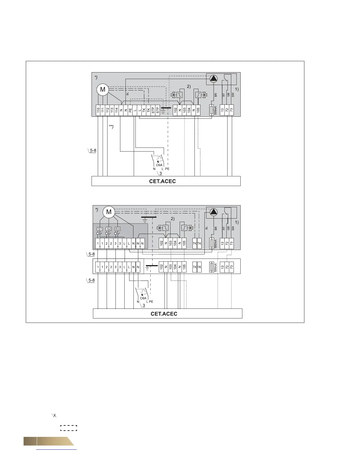
6.11 Electrical connection of FläktGroup miniature switches CET.ACEC for units with AC fans
6.11.1 Unit connecting terminals with a terminal strip and relay PCB
Fig. 6-60: Connecting terminals
1) Condensate pump is optional
2) Connect valves, if these are available in the unit configuration. Otherwise only fan control.
For a 4-pipe system, connect the heating valve to terminal 105, the cooling valve to terminal 103.
For a 2-pipesystem with the function "Only Heating", connect the heating valve to terminal 105.
For all other 2-pipe systems, connect the valve to terminal 103.
Connect dotted pipes only for units with valve sleeve.
*) The connections highlighted light gray were executed at the factory.
This view provides a better visualization of the switches.
**) Fan control (terminal diagram depending on selected rotational speed combination, refer to wiring diagram in the
terminal box)
Number of wires in the line: e.g.: 5 x 1.5 mm² NYM
relay PCB