HyPower-Geko Electrical connection
FläktGroup DC-2014-0022-GB 2018-05/R5 • Subject to modifications 83
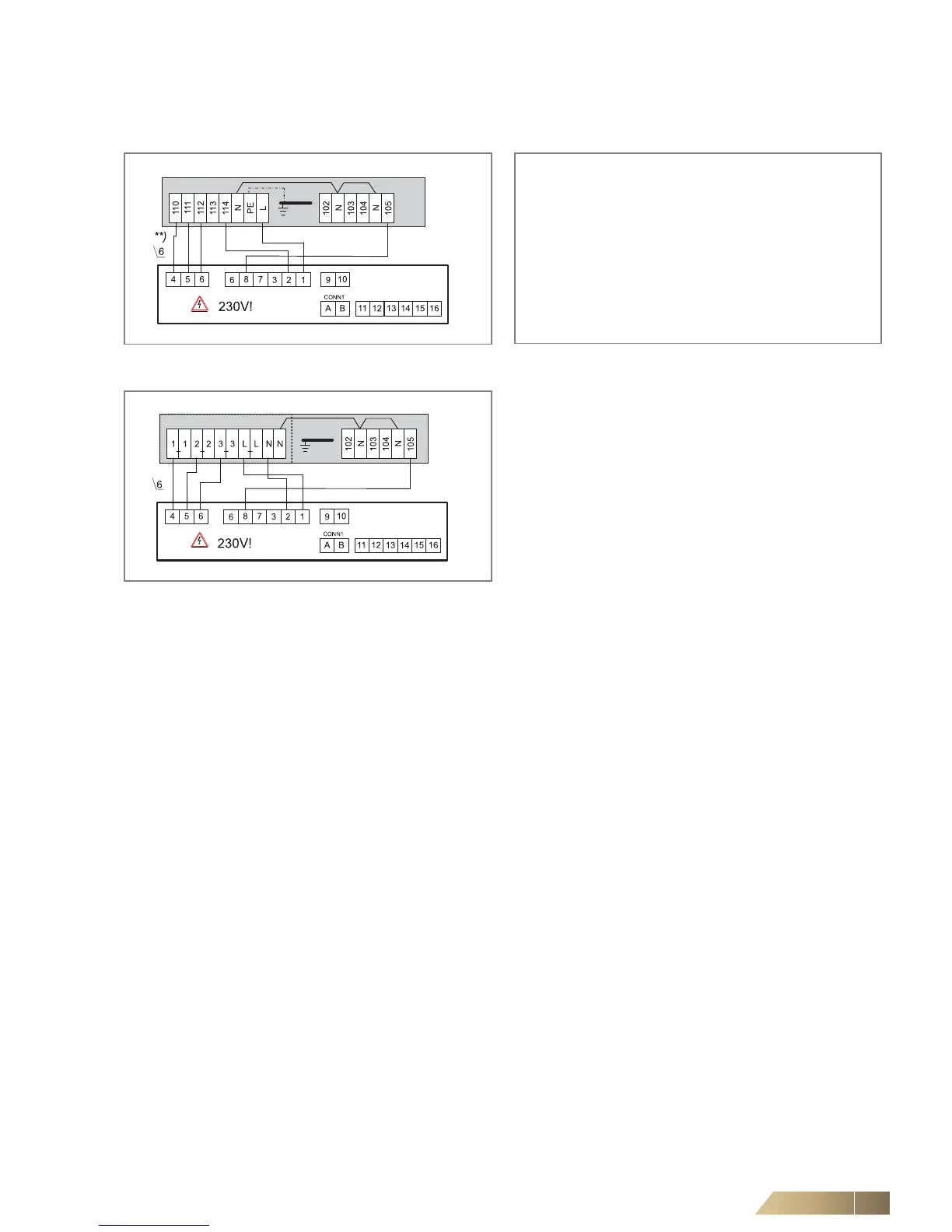
6.11.2 Operating mode Only Heating (2-pipe system)
**) Fan control (terminal diagram depending on selected rotational speed combination, see wiring diagram in the electric switch cabinet.
Fig. 6-61: Fan and valve control
(unit with terminal strip)
Configuration
Fig. 6-62: Fan and valve control
(unit with relay PCB)
Parameter 3: SEL0 = 14 and SEL2 = auto
(2-pipe system)
Parameter 4: SEL0 = 16 and SEL2 = OFF
(fan On/Off)
Parameter 5: SEL0 = 18 and SEL2 = auto
Parameter 7: SEL0 = 22 and SEL2 = auto
Parameter 8: SEL0 = 24 and SEL2 = 2
(without sensor)
Parameter 9: SEL0 = 26 and SEL2 = auto
(centrally or via sensor)