Electrical connection HyPower-Geko
84 FläktGroup DC-2014-0022-GB 2018-05/R5 • Subject to modifications
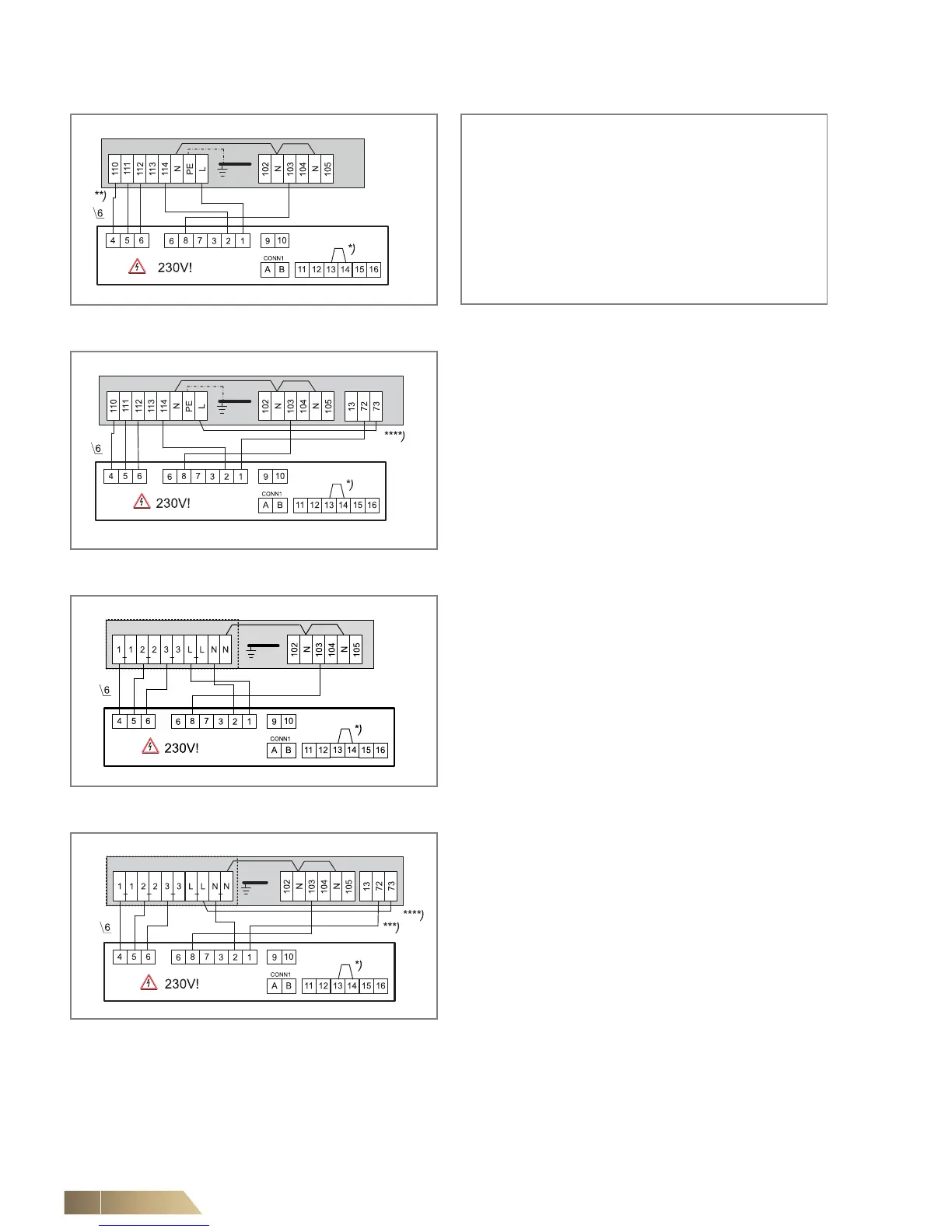
6.11.3 Operating mode Only Cooling (2-pipe system)
*) set jumper terminals 13, 14 on-site
**) Fan control (terminal diagram depending on selected rotational speed combination, see wiring diagram in the electric switch cabinet.
***) Signal contact condensate pump fault (for wiring on further units, refer to wiring diagram chapter 6.11.1).
****) In case of a condensate pump fault, the switch is automatically disconnected from the power supply.
Fig. 6-63: Fan and valve control
(unit with terminal strip)
Configuration
Fig. 6-64: Fan and valve control
(unit with terminal strip and condensate pump)
Fig. 6-65: Fan and valve control
(unit with relay PCB)
Fig. 6-66: Fan and valve control
(unit with relay PCB and condensate pump)
Parameter 3: SEL0 = 14 and SEL2 = auto
(2-pipe system)
Parameter 4: SEL0 = 16 and SEL2 = OFF
(fan On/Off)
Parameter 5: SEL0 = 18 and SEL2 = auto
Parameter 7: SEL0 = 22 and SEL2 = auto
Parameter 8: SEL0 = 24 and SEL2 = 2
(without sensor)
Parameter 9: SEL0 = 26 and SEL2 = auto
(centrally or via sensor)