HyPower-Geko Electrical connection
FläktGroup DC-2014-0022-GB 2018-05/R5 • Subject to modifications 81
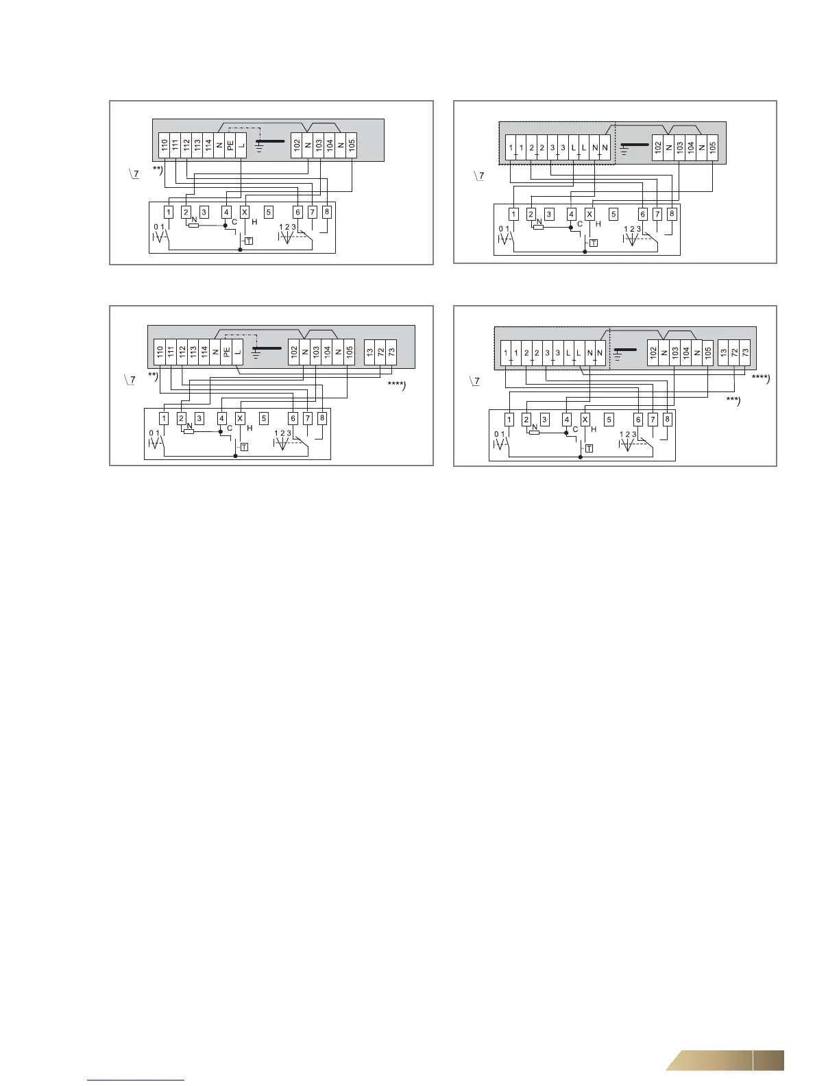
6.10.6 Operating mode Heating and Cooling (4-pipe system)
**) Fan control (terminal assignment depends on selected fan speed, see wiring diagram in electric switch cabinet.
***) Status contact for malfunction of condensate pump (for wiring of further units see wiring diagram in section 6.10.1).
****) With malfunction of condensate pump the switch is de-energized.
Fig. 6-56: Fan continuous mode and valve control
(unit with terminal strip)
Fig. 6-57: Fan continuous mode and valve control
(unit with relay PCB)
Fig. 6-58: Fan and valve control
(unit with terminal strip and condensate pump)
Fig. 6-59: Fan and valve control
(unit with relay PCB and condensate pump)
 Loading...

