Electrical connection HyPower-Geko
80 FläktGroup DC-2014-0022-GB 2018-05/R5 • Subject to modifications
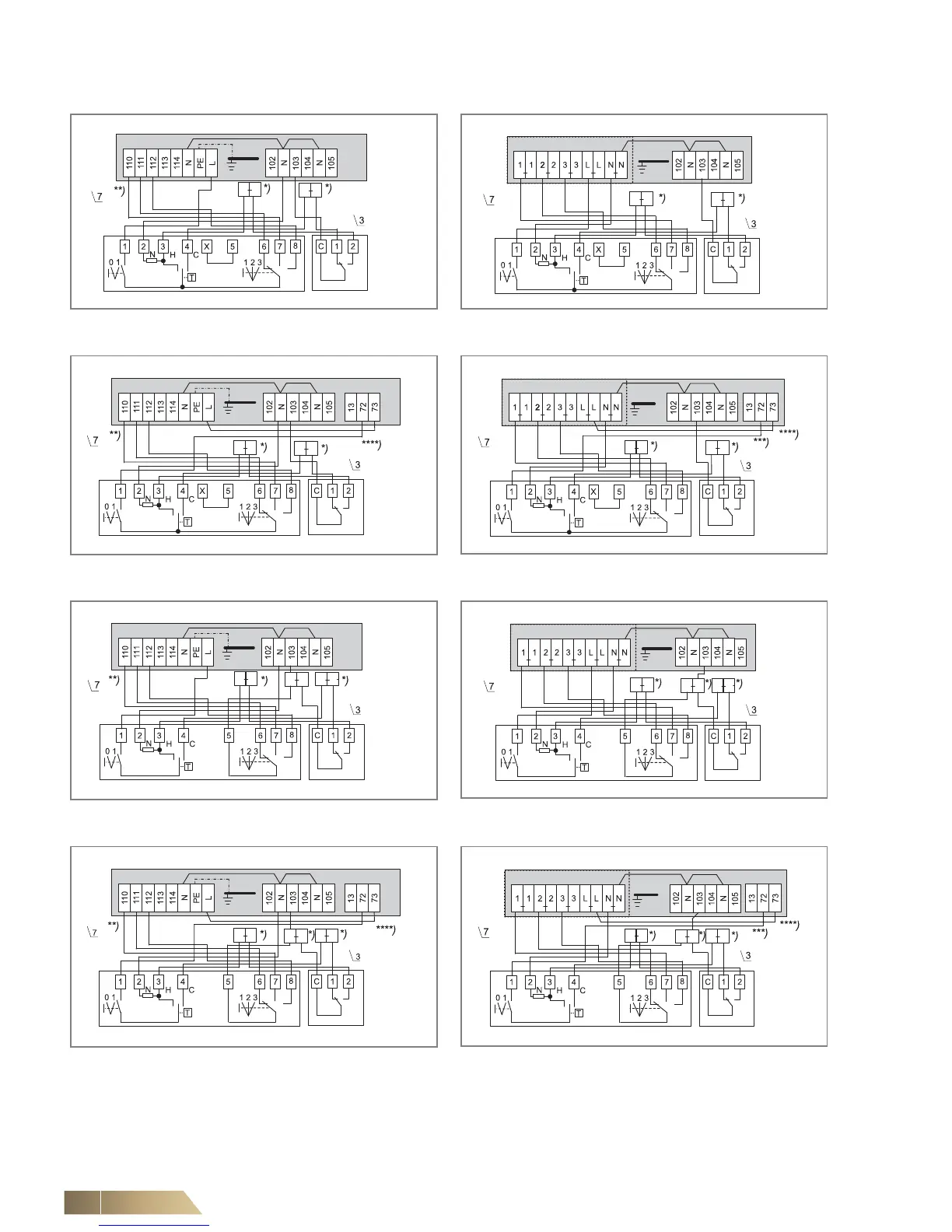
6.10.5 Operating mode Heating or Cooling (2-pipe system)
*) Intermediate terminals must be set by others on-site.
**) Fan control (terminal diagram depending on selected rotational speed combination, see wiring diagram in the electric switch cabinet.
***) Signal contact condensate pump fault (for wiring on further units, refer to wiring diagram chapter 6.10.1).
****) In case of a condensate pump fault, the switch is automatically disconnected from the power supply.
Fig. 6-48: Fan continuous mode and valve control
(unit with terminal strip)
Fig. 6-49: Fan continuous mode and valve control
(unit with relay PCB)
Fig. 6-50: Fan continuous mode and valve control
(unit with terminal strip and condensate pump)
Fig. 6-51: Fan continuous mode and valve control
(unit with relay PCB and condensate pump)
Fig. 6-52: Fan and valve control
(unit with terminal strip)
Fig. 6-53: Fan and valve control
(unit with relay PCB)
Fig. 6-54: Fan and valve control
(unit with terminal strip and condensate pump)
Fig. 6-55: Fan and valve control
(unit with relay PCB and condensate pump)
 Loading...

