HyPower-Geko Mounting
FläktGroup DC-2014-0022-GB 2018-05/R5 • Subject to modifications 37
4.4.6 Assembly of the intake/discharge sound attenuator
User instructions!
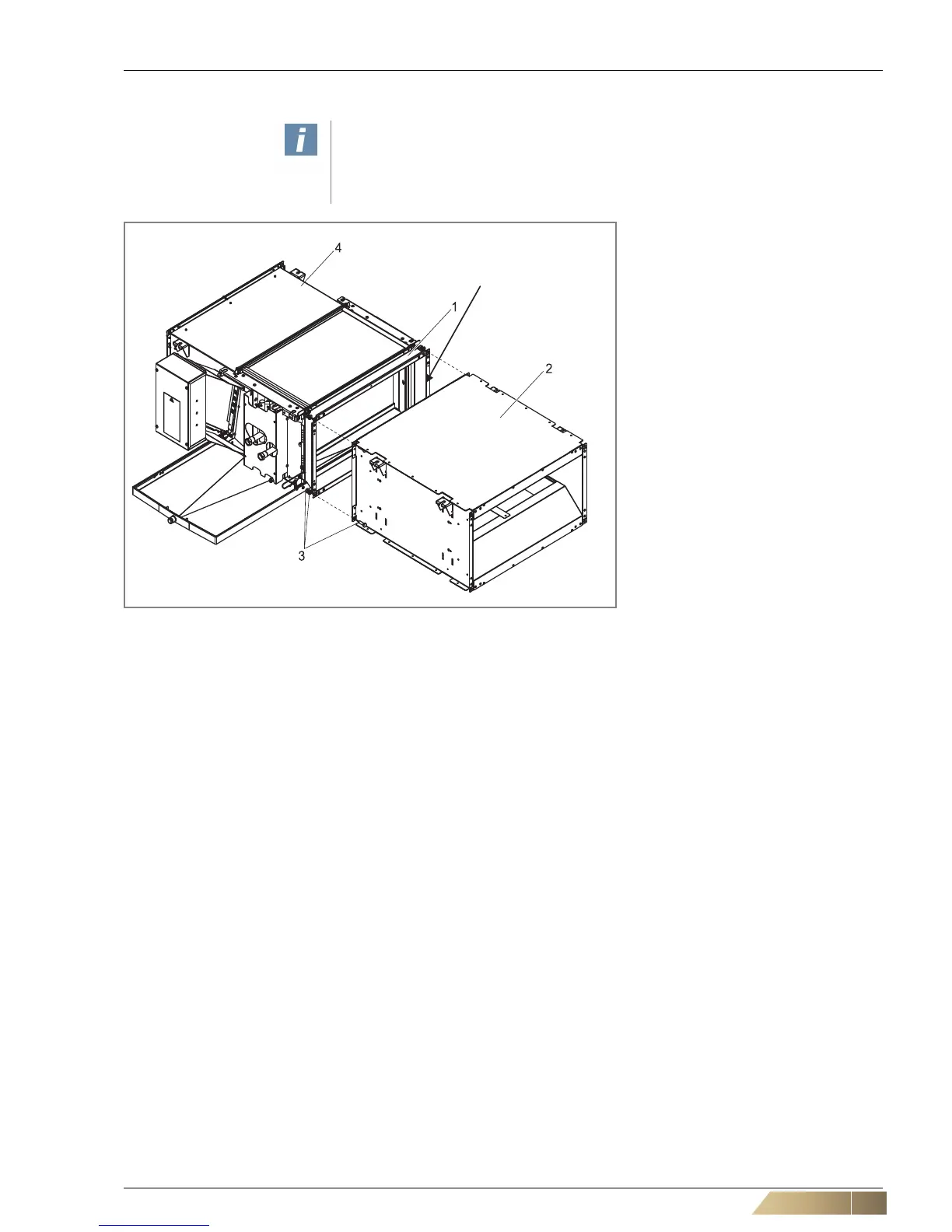
The intake/discharge sound attenuator is delivered with separately enclosed adhe-
sive tape provided for the duct seal between the flange of the sound attenuator and
the unit with fan section or the discharge-transition piece.
Pos. 1: Discharge transition piece
Pos. 2: Discharge sound attenuator
Pos. 3: Screw M8x25, washer, nut(4 pcs)
Pos. 4: Fan chamber
The intake sound attenuator
(ZGH.#A211) can be mounted on the
inlet side if the basic unit is furnished
with a fan section. The discharge
sound attenuator (ZGH.#A212) can be
mounted on the discharge side if the
unit is furnished with a discharge tran-
sition piece (ZGH.#A912).
• Stick the adhesive tape on to the
flange.
• Fasten the intake/discharge sound
attenuator to the unit with M8
screws (washers and nuts).
Fig. 4-14: Assembly of intake/discharge sound attenuator
 Loading...

