Hydraulic Connection HyPower-Geko
44 FläktGroup DC-2014-0022-GB 2018-05/R5 • Subject to modifications
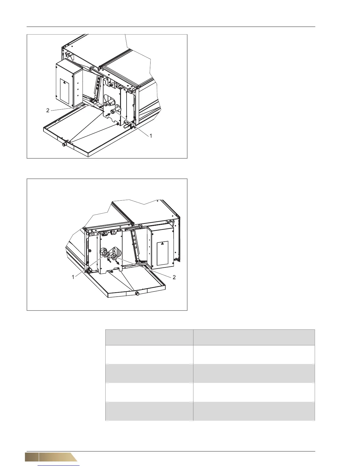
Pos. 1: Water inlet (internal screw thread, see Tab. 5-
1)
Pos. 2: Return line (internal screw thread, see
Tab. 5-1)
Fig. 5-7: Heat exchanger connections 2-pipe system, left connection
Pos. 1: Water inlet (internal screw thread, see Tab. 5-
1)
Pos. 2: Return line (internal screw thread, see
Tab. 5-1)
Fig. 5-8: Heat exchanger connections 2-pipe system, right connection
Type identification Connection fittings of the heat exchanger
- internal screw thread
GH11.#0W(W0,WC)#.#####
GH12.#0W(W0,WC)#.#####
GH13.#0W(W0,WC)#.#####
G 1/2"
G 1/2"
G 1/2"
GH21.#0W(W0,WC)#.#####
GH22.#0W(W0,WC)#.#####
GH23.#0W(W0,WC)#.#####
G 1/2"
G 1/2"
G 3/4"
GH31.#0W(W0,WC)#.#####
GH32.#0W(W0,WC)#.#####
GH33.#0W(W0,WC)#.#####
G 1/2"
G 3/4"
G 1"
GH41.#0W(W0,WC)#.#####
GH42.#0W(W0,WC)#.#####
GH43.#0W(W0,WC)#.#####
G 3/4"
G 1"
G 1"
Tab. 5-1: connecting dimensions of the fittings of the heat exchanger, 2-pipe system