Electrical connection HyPower-Geko
72 FläktGroup DC-2014-0022-GB 2018-05/R5 • Subject to modifications
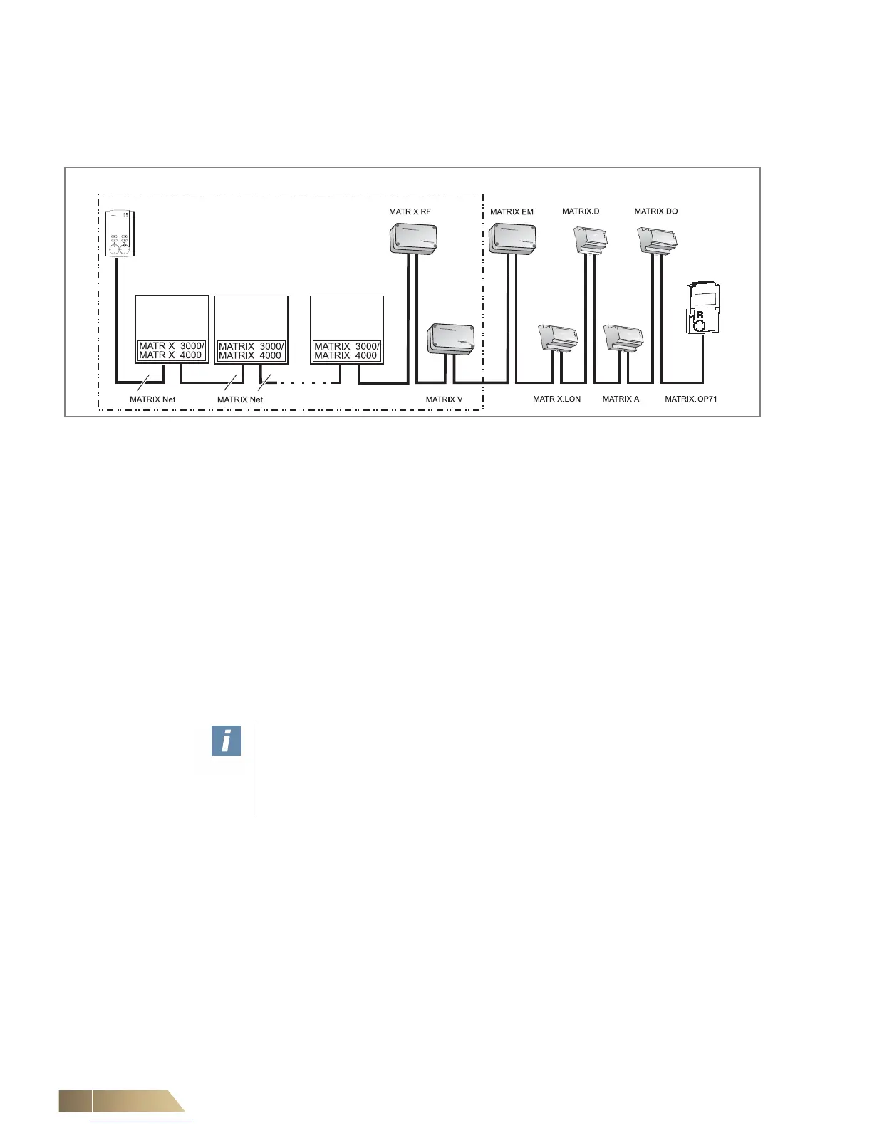
Group structure with MATRIX 3000 and/or MATRIX 4000 system
A group may be formed using the MATRIX 3000 and MATRIX 4000 systems. The
fig. 6-28 shows an example of a network consisting of a control panel, MATRIX 3000
system, MATRIX 4000 system and various global modules.
Fig. 6-28: Combined group structure of controller types MATRIX 3000 and MATRIX 4000
Any assignment and combination of the controllers/units is possible.
However, only MATRIX 3000 or only MATRIX 4000 controllers may be used.
We recommend the arrangement of the control panel as the first component of a group.
The group address is assigned:
– via the group address switch on the control panel – refer to the “Commissioning and
Testing” section in the relevant operation manual for MATRIX control panels
– on the printed circuit board of the MATRIX 3000/4000 controller – refer to the unit’s
operation manual.
Data assignment of MATRIX.LON module is performed via LON-side configuration.
The MATRIX.V, MATRIX.RF and MATRIX.EM modules are assigned to this group via
the group address switch – refer to the “Commissioning” section in this operation man-
ual or the corresponding manual for MATRIX Global Modules.
User instructions!
The combination of units with MATRIX 3000 and units with MATRIX 2000 systems
is permitted in this group setup – see “Group structure of the MATRIX 3000 system
in combination with the MATRIX 2000 system” on page 71. A combination of units
with MATRIX 4000 and units with MATRIX 2000 systems is not possible.