HyPower-Geko Electrical connection
FläktGroup DC-2014-0022-GB 2018-05/R5 • Subject to modifications 91
6.12.5 Sensors and control inputs
Danger of electrical current!
Extra-low voltage terminal strip (sensor and control input) is not galvanically sepa-
rated from the mains supply voltage. Mains potential on terminal and terminal strip.
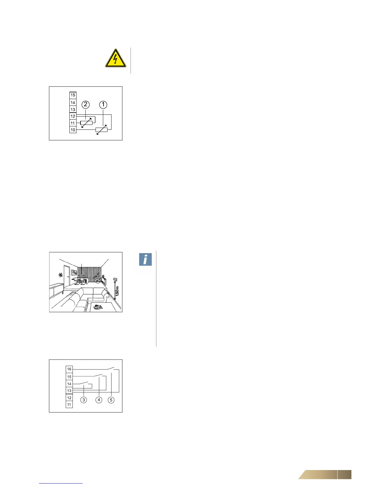
Fig. 6-83: Sensor connection
Room or return-air sensor connection (option) or inlet sensor
Pos. 1: Room or return-air sensor
Pos. 2: Inlet temperature sensor
• Connect the sensors in accordance with the wiring diagram.
Return-air sensor:
– If a return-air sensor is connected, the switch CET.ACEC must be correspondingly
configured. You will find details in the separate operation manual of the switch
CET.ACEC.
– For wiring a factory-mounted return-air sensor, connect relevant CET.ACEC termi-
nals with the corresponding terminals in the unit terminal box (refer to the unit con-
nection diagram for terminals).
Inlet temperature sensor:
– Installation of inlet sensor in supply line
– Fixation of sensor with an enclosed clip on the pipe. The clip is suitable for pipe sizes
of 15 mm.
– Following sensor installation, restore the pipe insulation.
Room sensor:
– Fix the casing in a suitable place (see fig. 6-84) using appropriate screws (max. M4).
– Connect the room temperature sensor according to the wiring diagram.
Fig. 6-84: Installation location
User instructions!
The installation site of the room temperature sensor is crucial for the pre-
cise control of room temperature. Therefore avoid mounting the sensor in
the following locations (refer to fig. 6-84):
– next to doors, windows, passageways etc., since intense movement of
air can cause incorrect measurements.
– Do not install on hot or cold walls (e.g. chimney, outside wall), since the
wall temperature can cause incorrect measurements,
– behind blinds and net curtains, as the insulating layers of air can cause
incorrect measurements.
– immediately near unit discharge grilles, since the discharge tempera-
ture can cause incorrect measurements.
Fig. 6-85: Control inputs
Control inputs enable or H/C changeover
Pos. 3: Input H/C changeover (instead of inlet sensor fig. 6-83, Pos 2)
Pos. 4: Presence input (absent = contact closed)
Pos. 5: Input enabling (active = contact open)
• Connect the control inputs in accordance with the wiring diagram.
– If a H/C change-over contact, presence contact, or enabling contact is connected,
the switch CET.ACEC must be correspondingly configured. You will find details in
the separate operation manual of the switch CET.ACEC.