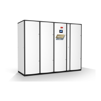
Multi -DENCO
®
Commissioning Record
A-Version
Yes/No
V V
V V
V V
V
Number Controller Software Version Number
Yes / No Denconet Configuration Type
Number Number
Type Number
Number Number
°C % RH
°C °C
% RH % RH
°C
Pa °C
bar °C
bar °C
T or TH P or PI
IP Address BMS Address
Check installation complies with Operation Manual & Approved Code of Practice-DX Installations
Check & confirm interconnecting control and power cabling is correct
Initial Box =
Initial Box =
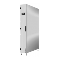
Heat Rejection Serial No.
Ambient Temp Calibration
Control Type
Incoming L2 - N
Incoming L2 - L3 Incoming L3 - N
Section A: For completion by commissioning engineer for each u
nit on site before starting commissioning.
Check & confirm that pipe connections into condensers are correctly orientated i.e. refrigerant liquid line is
nearest to the coil air inlet side. Where condensers are in a tandem configuration, the condensers must be at
the same level, and liquid plus discharge branches must be of equal length
Initial Box =
All instrumentation is covered by a current calibration certificate - including pressure gauges, thermometers,
vacuum gauges, airflow meters.
Section B: For completion by the Commissioning Engineer for each unit on site
Check & confirm all electrical connections are secure
Confirm a signed Pressure Test Certificate has been issued by installer Initial Box =
Heat Rejection Serial No.
Suction Pressu
re Calibration
AHU Serial No.
AHU Location
Supply Air Hum Calibration
Display Software Version
Discharge Temp Calibration
Suction Temp Calibration
AHU Site Reference No.
Denconet enabled
Incoming L1 - N
Incoming L1 - L3
Control Voltage
Initial Box =
Check & confirm pre-formed discharge line oil traps are fitted (traps manufactured from fittings or bent tube
are not acceptable).
Check software version is installed Initial Box =
Available kW
Network Number of Display
Initial Box =
Air Flow Monitoring Calibration
Supply Air Temp Calibration Ret
urn Air Temp Calibration
Heat Load Available During Commissioning Process
Project Number
End User's Name
Site Address
Temperature Set Point Humidity Set Point
Controls
Subnet MaskInterface Card
FläktGroup Contact
Network Number of Unit
Heat Rejection Location
Electrical Power Supply
Return Air Hum Calibration
COMMISSIONING MUST CEASE IF CONDENSERS OR OIL TRAPS DO NOT MEET REQUIREMENTS
Initial Box =
AHU Model No. Heat Rejection Model No.
Incoming L1 - L2
Liquid Line Temp Calibration
Discharge Pressure Calibration
Control Type
Page 2 of 4
Based on DQA800