Multi-DENCO Medium Connections
FläktGroup DC-2013-0101-GB • Subject to modifications • R5-08/2020 61
6.2.2 Material quality
For refrigeration pipework:
– Copper tube quality must be the equivalent of EN 12735-1
– Refrigeration grade copper must be used
– Pipework must be cleaned and dehydrated
– Use of joints, bends or sets must be kept to a minimum
– Bends or sets are to be machine pulled to approved radius at all times
– Only properly swaged joints can be used (butt joints are not allowed)
– Manufactured bends are not recommended
– It is recommended to use half-hard straight lengths of copper instead of coils.
6.2.3 Sizing
Pipe sizing When sizing pipework, consideration should be given with regards to adequate oil
return during all conditions.
It is also important that the pressure drops in pipework are minimised to avoid unnec-
essary decreases in capacity. Larger pipe sizes reduce gas velocity and make oil
return more difficult to accomplish. Smaller pipe diameters increase oil velocity, but will
be more susceptible to high pressure drops.
A-Version & F-Version
Discharge Line: Recommended pressure drop = 1.0K, Max pressure drop = 2.5K
Liquid Line: Max pressure drop = 1.5K
NOTE!
Prior to installation it is particularly important to check the correct size refrigeration
pipework is being installed. Contact your local representative if you are unsure.
NOTE!
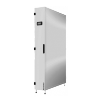
Only the pipe sizes listed below are ALLOWABLE for each size. ONLY these sizes
MUST be used for both horizontal and vertical risers. This table is for REFERENCE
ONLY.
NOTE!
FINAL and ULTIMATE responsibility for pipe sizing is of the contractor or installer.
The below table is for GUIDANCE ONLY to specify the range of sizes applicable. It
is necessary that suitably qualified engineers conduct their own, separate calcula-
tions to determine the sizing suitable for the application.
Metric (mm) 10 12 16 18 22 28 35 42 2 x 22 2 x 28
Imperial (Inch) 3/8 1/2 5/8 3/4 7/8 1-1/8 1-3/8 1-5/8 2 x 7/8 2 x 1-1/8
010
Liquid zzzz
Discharge z z z
018
Liquid zzz
Discharge z z
030
Liquid zzz
Discharge z z z
045
Liquid zzz
Discharge z z z
065
Liquid zz
Discharge z z
092
Liquid zz
Discharge z z z
130
Liquid z
z
Discharge
z
z z
Tab. 6-1