Medium Connections Multi-DENCO
62 FläktGroup DC-2013-0101-GB • Subject to modifications • R5-08/2020
W-Version & P-Version
X-Version & H-Version (DENCO-OfficeCool)
Only valid for unit combination listed within table. For any other version please contact your local sales/service support.
6.2.4 Installation with 2 condensers
On Fig. 6-1 and Fig. 6-2 the labels are as follows:
1 Discharge line (hot gas) from the Multi-DENCO indoor unit
2 Branches of discharge line
3 Liquid Line returning to the Multi-DENCO indoor unit
4 Branches of liquid line
For any installation with 2 condenser in tandem configuration:
• Both must be placed on the same level
• Pipes 2 and 4 (pipework after the 'T-Joint') should be 1 pipe diameter size smaller
than pipes 1 and 3 respectively (see Tab. 6-1 and Tab. 6-3)
• Ensure that A = A and B = B
• For Horizontal Airflow: A + B < 5 metres
• For Vertical Airflow: A < 5 metres and B < 5 metres
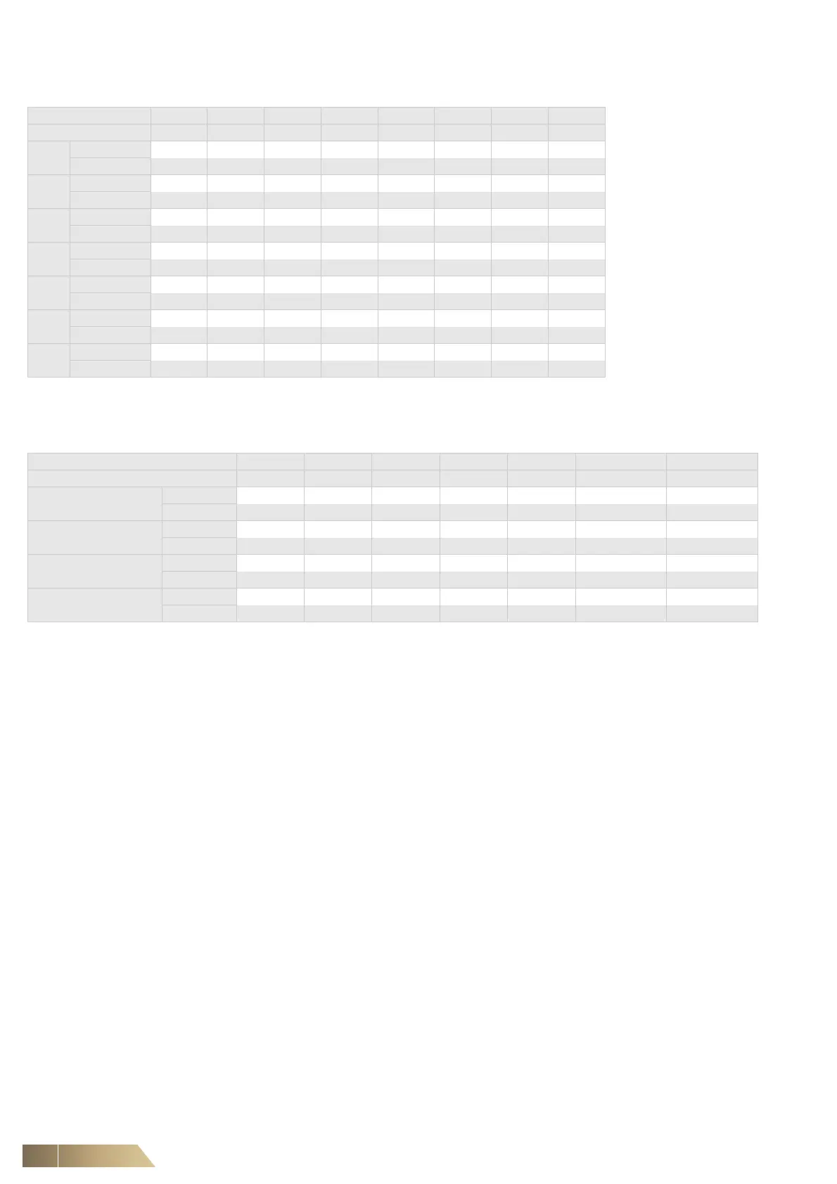
Metric (mm) 10 12 16 18 22 28 35 42
Imperial (Inch) 3/8 1/2 5/8 3/4 7/8 1-1/8 1-3/8 1-5/8
010
Liquid z
Discharge z
018
Liquid z
Discharge z
030
Liquid z
Discharge z
045
Liquid z
Discharge z
065
Liquid z
Discharge z
092
Liquid z
Discharge z
130
Liquid z
Discharge
z
Tab. 6-2
Metric (mm) 10 12 16 18 22 2 x 12 2 x 22
Imperial (Inch) 3/8 1/2 5/8 3/4 7/8 2 x 1/2 2 x 7/8
010
1 x PUHZ-ZRP100YKA
Expansion z
Suction z
018
1 x PUHZ-RP200YKA
Expansion z
Suction z
030
1 x PUHZ-RP250YKA
Expansion z
Suction z
045
2 x PUHZ-RP250YKA
Expansion z
Suction z
Tab. 6-3