Electrical Connections Multi-DENCO
88 FläktGroup DC-2013-0101-GB • Subject to modifications • R5-08/2020
7.2.5 Electrical connections between components (P-Version)
The Multi-DENCO P-Version is delivered in 2 parts, therefore interconnecting electrical
wiring must be completed on site:
– Locate the incomplete wiring for the water pump within the watercool module section
– Route the cables to the control panel make sure to be clear of any moving parts
(fans) and away from any heat sources
– Connect the wires to the associated connection points in the control panel as per the
contract wiring diagram
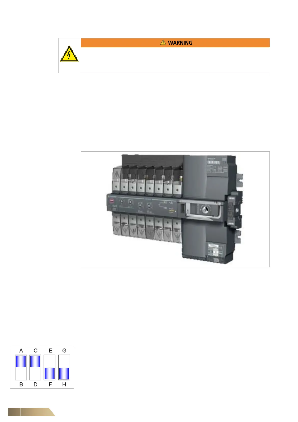
7.2.6 Units with a Automatic Transfer Switch (ATS)
Fig. 7-1
The Automatic Transfer Switch (ATS) allows for 2 mains power supplies to be con-
nected with the Multi-DENCO unit. In the event of a power failure, the switch will switch
from the "Primary" power supply to the "Secondary" power supply. During this process,
the power supply to the unit is disconnected. The ATS has an inbuilt, adjustable timer
to set the time period before it can check and return to the "Primary" power supply.
A manual over-ride can be performed to choose the power supply by lifting the clear
plastic cover and using the Allen key provided. The clear plastic cover must be fully
closed to activate the automatic change-over function.
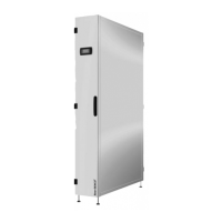
The DIP switches should be configured like the following:
Fig. 7-2
Incomplete electrical cables are hazardous:
• Do NOT connect the mains power supply before completing the instructions in
chapter 7.2.5
A = 3 phase power supply
C = 50 Hz
F = 2 seconds delay in the "OFF" position during transfer procedure
H = Transformer/Transformer type of supply