FLUXUS F70x 7 Connection
74 UMFLUXUS_F7V4-6-2EN, 2017-10-01
Temperature probe
• Remove the blind plug for the connection of the temperature probe (see Fig. 7.34).
• Open the cable gland of the temperature probe (see Fig. 7.35 and Tab. 7.12). The compression part remains in the cap
nut.
• Push the cable of the temperature probe through the cap nut and the compression part.
• Prepare the cable.
• Cut the external shield and brush it back over the compression part.
• Screw the gasket ring side of the reducer into the junction box.
• Tightly screw the basic part into the reducer.
• Insert the cable into the junction box.
• Fix the cable gland by screwing the cap nut onto the basic part.
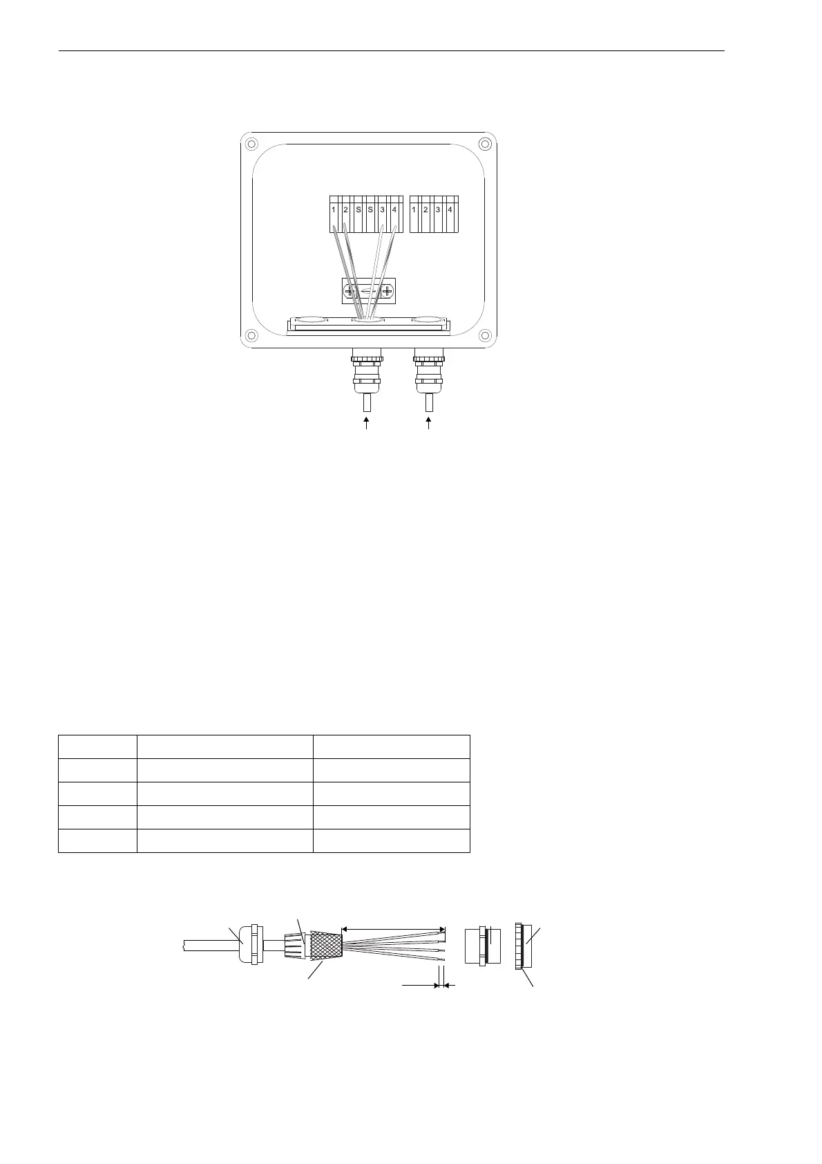
• Connect the temperature probe to the terminals of the junction box (see Fig. 7.34 and Tab. 7.16).
Fig. 7.34: Junction box JBT2, JBT3
Tab. 7.16: Terminal assignment of the junction box
terminal extension cable (KL2) temperature probe (KL1)
1red red
2gray red/blue
3white white
4 blue white/blue
Fig. 7.35: Preparation
KL2
KL1
extension cable
temperature probe
external shield,
brushed back
cap nut
compression
part
basic part
110 mm
reducer
gasket ring side
7 mm
 Loading...


