FLUXUS F70x 7 Connection
78 UMFLUXUS_F7V4-6-2EN, 2017-10-01
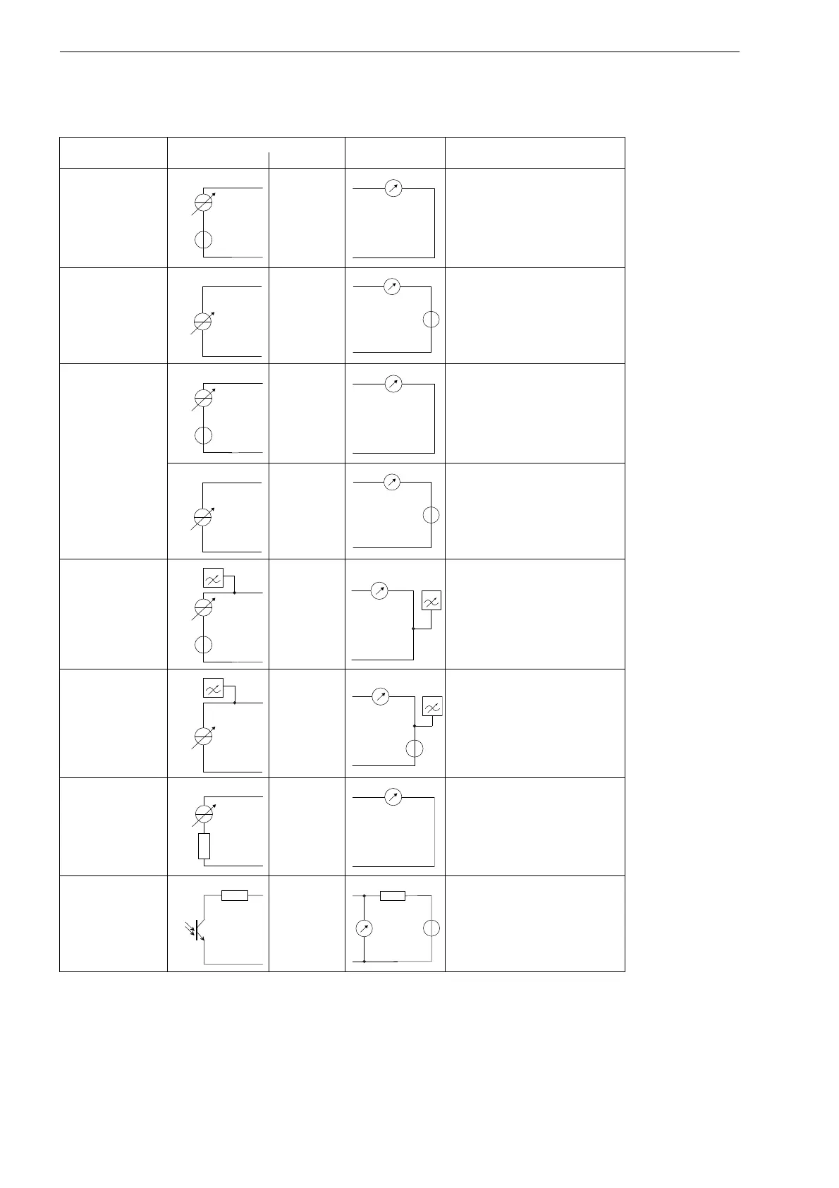
Tab. 7.19: Circuits of the outputs
output transmitter external circuit remark
internal circuit connection
active current
loop Px+
Px-
R
ext
< 500 Ω
passive current loop
Px+
Px-
U
ext
=
4...24 V
U
ext
> 0.021 A
.
R
ext
[Ω] + 4 V
example:
U
ext
= 12 V
R
ext
= 0...380 Ω
switchable current
loop
1
All switchable cur-
rent outputs are
switched to active or
passive mode at the
same time.
Px+
Px-
active current
loop:
R
ext
< 350 Ω
Px+
Px-
passive current loop:
U
ext
=
8...30 V
U
ext
> 0.021 A
.
R
ext
[Ω] + 8 V
example:
U
ext
= 12 V
R
ext
= 0...190 Ω
HART (active)
Px+
Px-
U
i
= 24 V
HART (passive)
Px+
Px-
U
ext
= 10...24 V
voltage output
Px+
Px-
R
i
= 500 Ω
R
ext
> 2 MΩ
If R
ext
is lower, the accuracy is lo-
wer than specified.
frequency output
Px+
Px-
U
ext
= 5...24 V
R
c
[kΩ] = U
ext
/I
c
[mA]
I
c
= 1...4 mA
P1...P4: R
i
= 66.5 Ω
The number, type and connections of the outputs are customized.
R
ext
is the sum of all ohmic resistances in the circuit (e.g. resistance of the conductors, resistance of the ampere-
meter/voltmeter).
ƒ
G
 Loading...


