7 Connection FLUXUS F70x
UMFLUXUS_F7V4-6-2EN, 2017-10-01 79
1
For the display and the setting of the switchable current loop see section 18.1.
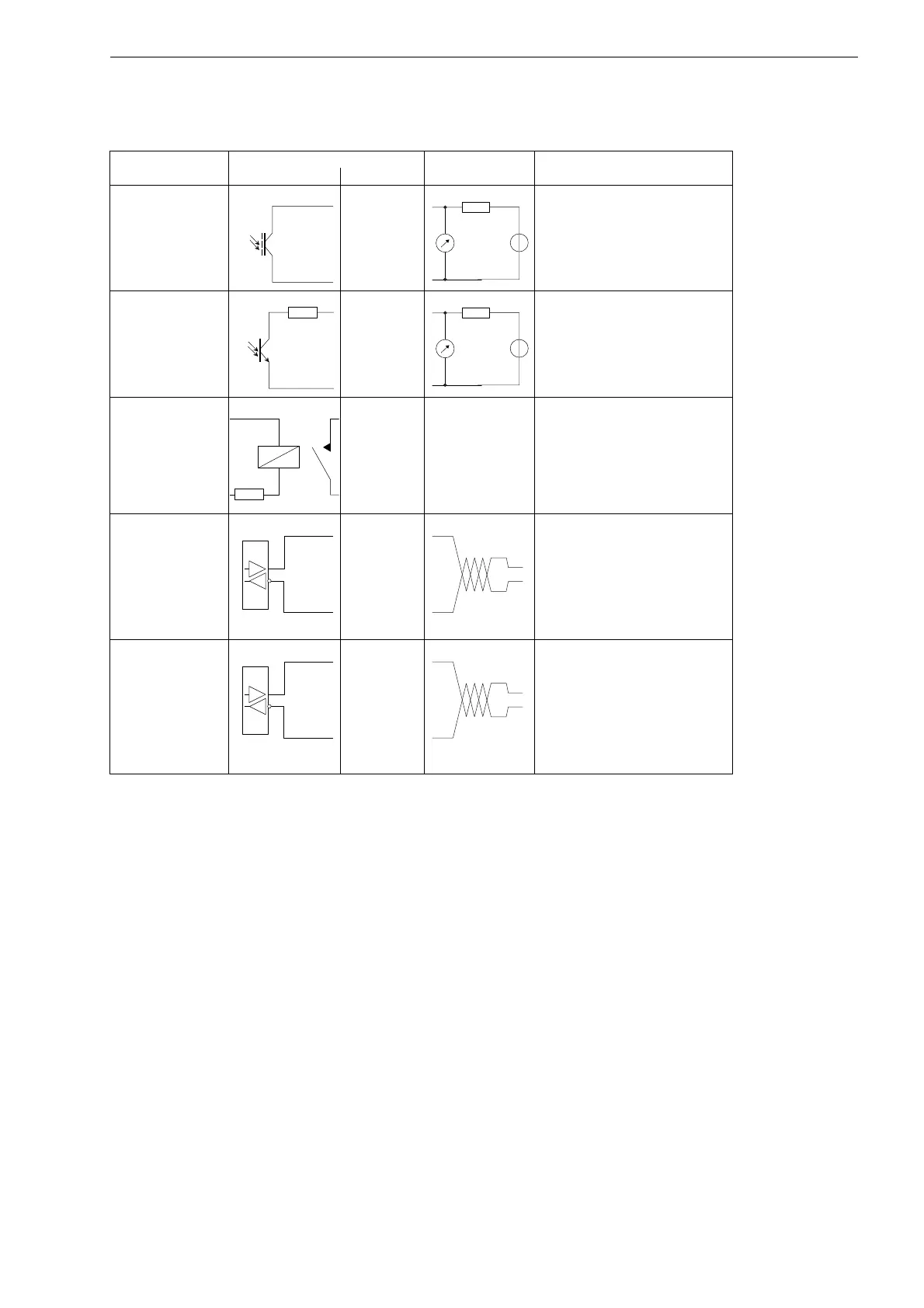
binary output (opto-
relay)
F704
F705
F706
Pxa
Pxb
U
ext
≤ 26 V
I
c
≤ 100 mA
binary output (open
collector) Px+/Pxa
Px-/Pxb
U
ext
= 5...24 V
R
c
[kΩ] = U
ext
/I
c
[mA]
I
c
= 1...4 mA
P1...P4: R
i
= 22 Ω
binary output (Reed
relay) Px+/Pxa
Px-/Pxb
U
max
= 48 V
I
max
= 100 mA
P1...P4: R
i
= 22 Ω
RS485
F704
F705
F706
A+
B-
120 Ω
termination resistor
shield 101
RS485
F709
4A+
4B-
120 Ω
termination resistor
shield 43
Tab. 7.19: Circuits of the outputs
output transmitter external circuit remark
internal circuit connection
The number, type and connections of the outputs are customized.
R
ext
is the sum of all ohmic resistances in the circuit (e.g. resistance of the conductors, resistance of the ampere-
meter/voltmeter).
 Loading...


