FLUXUS F70x 7 Connection
82 UMFLUXUS_F7V4-6-2EN, 2017-10-01
FLUXUS F709
• Prepare the input cable.
• Connect the input cable to the terminals of the transmitter (see Fig. 7.4, Fig. 7.44 and Tab. 7.21).
At full load (20 mA), a voltage of 22.9 V DC (FLUXUS F704, F705, F706) or 13.9 V DC (FLUXUS F709) is available for the
supply of the passive current source.
For the assignment and the activation of the current input see chapter 17.
7.5.3 Binary Input
The transmitter can be equipped with 1 or 2 binary inputs. Via the binary outputs, it is possible to remotely trigger some
functions of the transmitter (see section 11.10).
FLUXUS F704, FLUXUS F705, FLUXUS F706
For the connection of the input cable to the transmitter see box Cable connection S. 75, Fig. 7.1 or Fig. 7.2, Fig. 7.42 or
Fig. 7.43 and Tab. 7.22)
.
FLUXUS F709
• Prepare the input cable.
• Connect the input cable to the terminals of the transmitter (see Fig. 7.4, Fig. 7.44 and Tab. 7.22).
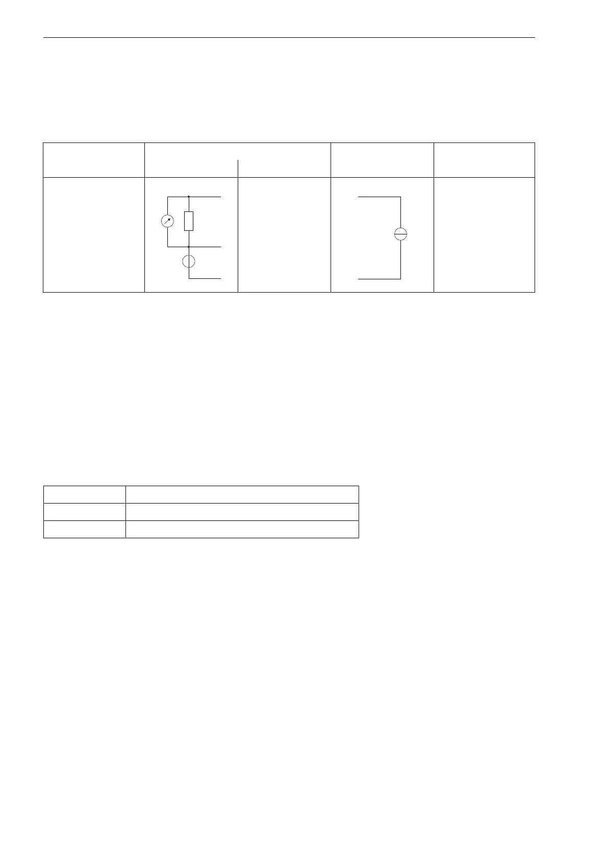
Tab. 7.21: Connection of a passive current source
input transmitter external circuit comments
internal circuit connection
current input
TxA
TxB (not connected)
Txb
max. permanent
overcurrent: 100 mA
Tab. 7.22: Connection of the binary inputs
binary input terminals
S1 P1+, P1-
S2 P2+, P2-
 Loading...


