16 Advanced functions
16.12 Behavior of the alarm outputs FLUXUS G809
2020-06-25, UMFLUXUS_G809V2-2EN
146
Press 3 times key CLR during the measurement to set all alarm outputs to idle state. Alarm outputs whose switching con-
dition is still met will be activated again after 1 s. This function is used to reset alarm outputs of the type HOLD if the switch-
ing condition is no longer met.
By pressing key BRK, the measurement is stopped and the main menu is selected. All alarm outputs will be de-energized,
independently of the programmed idle state.
16.12.3 Alarm outputs during transducer positioning
At the beginning of the transducer positioning (bar graph display), all alarm outputs switch back to the programmed idle
state.
If the bar graph is selected during the measurement, all alarm outputs will switch back to the programmed idle state.
An alarm output of the type HOLD that has been activated during the previous measurement will remains in idle state after
the transducer positioning if its switching condition is no longer met.
The switching of the alarms into idle state will not be displayed.
16.12.4 Alarm outputs during measurement
An alarm output with switching condition MAX or MIN will be updated max. once per second to avoid humming (i.e. fluctua-
tion of the measured values around the value of the switching condition).
An alarm output of the type NON-HOLD will be activated if the switching condition is met. It will be deactivated if the switch-
ing condition is no longer met. The alarm remains activated for at least 1 s even if the switching condition is met for a
shorter period of time.
Alarm outputs with the switching condition QUANT. will be activated if the limit is reached.
Alarm outputs with the switching condition ERROR will only be activated after several unsuccessful measuring attempts.
Therefore, typical short-term disturbances of the measurement (e.g., switching on of a pump) will not activate the alarm.
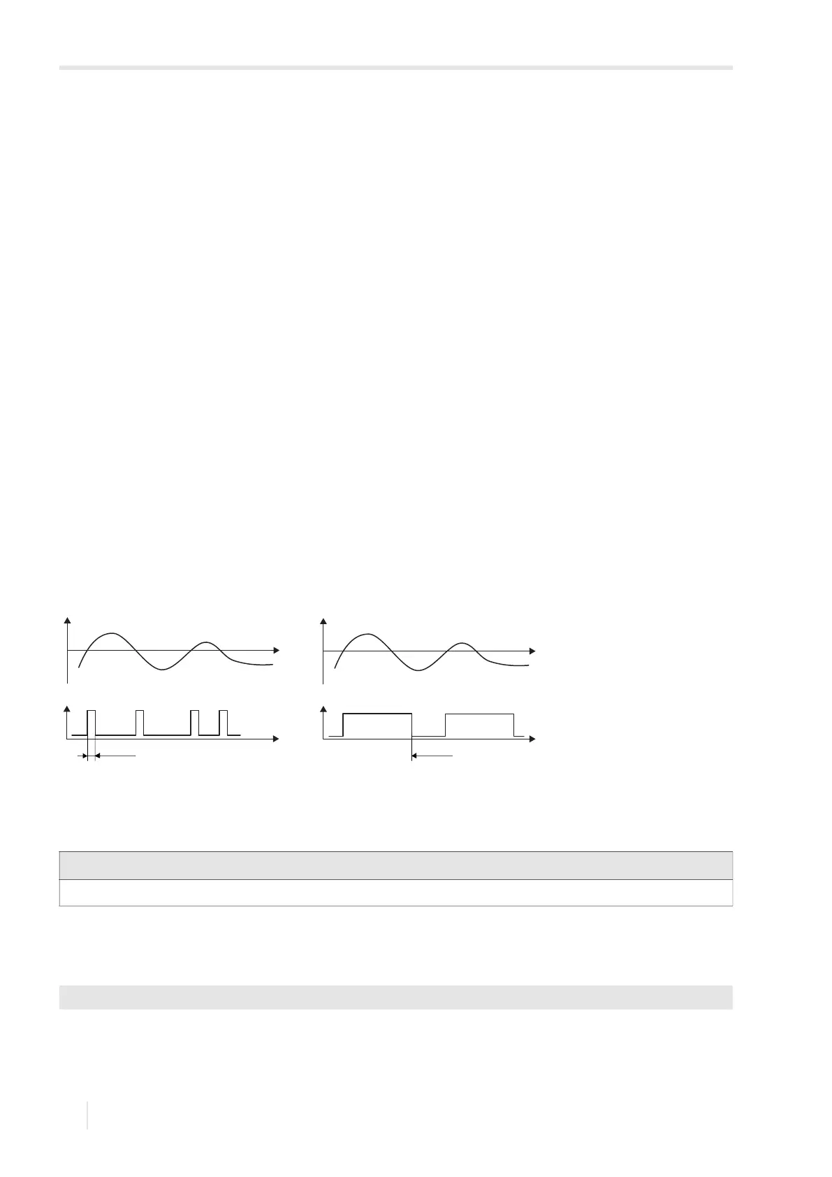
Alarm outputs with the switching condition +→- -→+ and the type NON-HOLD will be activated with each change of the flow
direction for approx. 1 s, see Fig. 16.1.
Alarm outputs with the switching condition +→- -→+ and of the type HOLD will be activated after the first change of the flow
direction. They can be switched back by pressing key CLR 3 times, see Fig. 16.1.
When adjusting to changed measurement conditions e.g, a substantial increase of the fluid temperature, the alarm will not
be switched. Alarm outputs with the switching condition OFF will be set automatically to the switching function NO Cont.
The alarm state can be displayed after the configuration of the alarm outputs and during the measurement. This function is
activated in Special Funct.\SYSTEM settings\Dialogs/Menus. The activation of this function is recommended
when alarm outputs have to be reconfigured frequently.
• Select the menu item SHOW RELAIS STAT.
• Select on to activate the alarm state indication.
• Press ENTER.
Fig. 16.1: Behavior of a relay when the flow direction changes
Notice!
There is neither a visual nor an acoustic indication of the alarm output switching.
Special Funct.\SYSTEM settings\Dialogs/Menus\SHOW RELAIS STAT
flow flow
type NON-HOLD type HOLD
approx. 1 s
reset of the alarm
(3 times key CLR)