3 General principles
3.3 Acoustic penetration FLUXUS G809
2020-06-25, UMFLUXUS_G809V2-2EN
16
3.3 Acoustic penetration
The pipe has to be acoustically penetrable at the measuring point. The acoustic penetration is given when pipe and fluid
do not attenuate the sound signal so strongly that it is completely absorbed before reaching the second transducer.
The attenuation caused by the pipe and the fluid depends on:
• kinematic viscosity of the fluid
• the proportion of liquids and solids in the fluid
• deposits on the inner pipe wall
• pipe material
The following requirements have to be met at the measuring point:
• no solid deposits in the pipe
• no accumulation of liquid (condensate), e.g., before orifice plates or at pipe sections located lower
Observe the following notes on the selection of the measuring point:
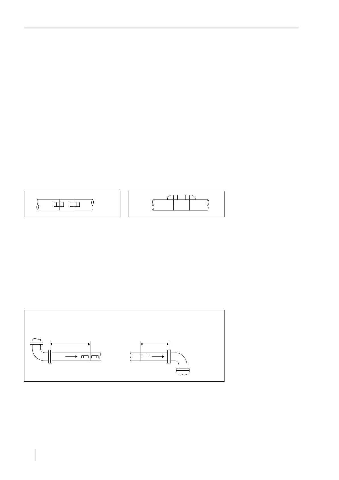
Horizontal pipe
Select a measuring point where the transducers can be mounted laterally on the pipe, allowing the sound waves to propa-
gate horizontally in the pipe. Thus, solids or liquid on the bottom of the pipe or gas bubbles in the pipe's upper part are pre-
vented from influencing the propagation of the signal (see Fig. 3.8 and Fig. 3.9).
3.4 Undisturbed flow profile
Some flow elements (e.g., elbows, valves, pumps, reducers) distort the flow profile in their vicinity. The axisymmetrical
flow profile in the pipe needed for correct measurement is no longer given. A careful selection of the measuring point helps
to reduce the impact of disturbance sources.
It is most important that the measuring point is chosen at a sufficient distance from any disturbances. Only then it can be
assumed that the flow profile in the pipe is fully developed. However, measuring results can be obtained even if the
recommended distance to disturbances cannot be met for practical reasons (no ideal inflow, see section 16.4).
The recommended straight inlet and outlet pipe lengths for different types of flow disturbance sources are shown in the ex-
amples in Tab. 3.1.
Fig. 3.8: Recommended transducer
mounting position
Fig. 3.9: Disadvantageous transducer
mounting position
Tab. 3.1: Recommended distance from disturbance sources
D – nominal pipe diameter at the measuring point
l – recommended distance between disturbance source and transducer position
disturbance source: 90° elbow
inlet: l ≥ 10 D outlet: l ≥ 5 D
l l