7 Connection
7.3 Outputs FLUXUS G809
2020-06-25, UMFLUXUS_G809V2-2EN
76
7.2.1 Cable connection (FLUXUS G809**-A1 and FLUXUS G809**-A1A only)
• Remove the blind plug to connect the cable to the transmitter.
• Prepare the cable with an M20 cable gland.
• The used cable has to have a wire cross-section of 0.25…2.5 mm².
• Push the cable through the cap nut, compression part and basic part of the cable gland.
• Insert the cable into the housing of the transmitter.
• Screw the sealing ring side of the basic part into the transmitter housing.
• Fix the cable gland by screwing the cap nut onto the basic part.
• Connect the cable to the terminals of the transmitter.
7.3 Outputs
• Connect the output cable to the transmitter.
For the connection of the output cable to the transmitter, see section 7.2.1, Fig. 7.16 and Tab. 7.13.
Fig. 7.15: Cable gland
1 – cap nut
2 – compression part
3 – basic part
Important!
The max. permissible voltage between the outputs and against PE is 60 V DC (permanent).
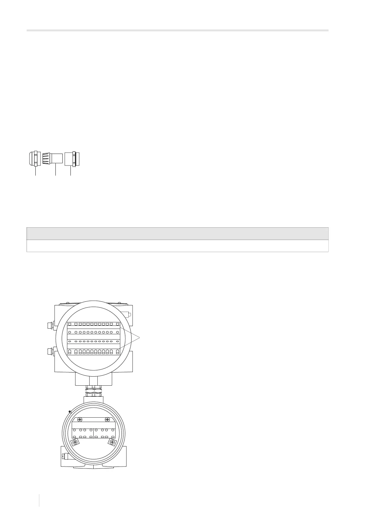
Fig. 7.16: Connection of the outputs on the transmitter
1 – outputs
21 3
AR
L
(+)
N
(-)
PE
ARS AVAVS BR BRS BVBVS
1