7 Connection
FLUXUS G809 7.3 Outputs
77
UMFLUXUS_G809V2-2EN, 2020-06-25
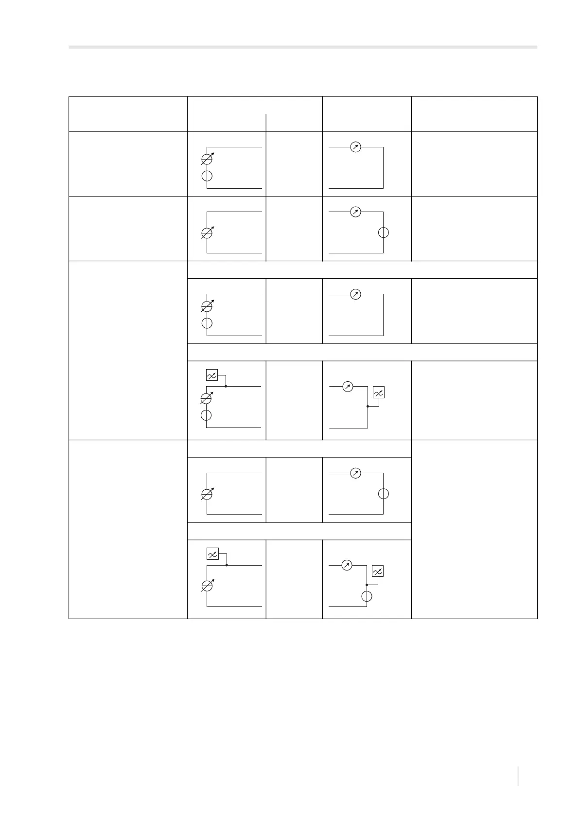
Tab. 7.13: Circuit of the outputs
output transmitter external circuit remark
internal circuit connection
active current output
G809**-A1
G809**-F1
R
ext
< 500 Ω
passive current output
G809**-A1
G809**-F1
U
ext
= 4…26.4 V
U
ext
> 0.021 A
.
R
ext
[Ω] + 4 V
example:
U
ext
= 12 V
R
ext
≤ 380 Ω
active current output/HART
G809**-A1
G809**-F1
current output
R
ext
< 500 Ω
HART
U
int
= 24 V
passive current output/HART
G809**-A1
G809**-F1
current output U
ext
= 7…30 V
U
ext
> 0.022 A
.
R
ext
[Ω] + 7 V
example:
U
ext
= 12 V
R
ext
≤ 227 Ω
current during transmitter fault:
I
fault
= 3.2…3.5 mA
HART
The number, type and the connections of the outputs depend on the order.
R
ext
is the sum of all ohmic resistances in the circuit (e.g., resistance of the conductors, resistance of the amperemeter/voltmeter).
+
-
I1/I2: 2/4 (+)
I1/I2: 1/3 (-)
mA
-
+
I1/I2: 1/3 (-)
I1/I2: 2/4 (+)
mA
U
ext
+
-
+
-
I1/I2: 2/4 (+)
I1/I2: 1/3 (-)
mA
-
+
-
+
U
int
I1: 2 (+)
I1: 1 (-)
mA
I1/I2: 1/3 (-)
I1/I2: 2/4 (+)
mA
U
ext
+
-
I1: 1 (-)
I1: 2 (+)
mA
U
ext
+
-