15
OPERATION (continued)
NORMAL OPERATION MODE (continued)
Diagnostic Mode (continued)
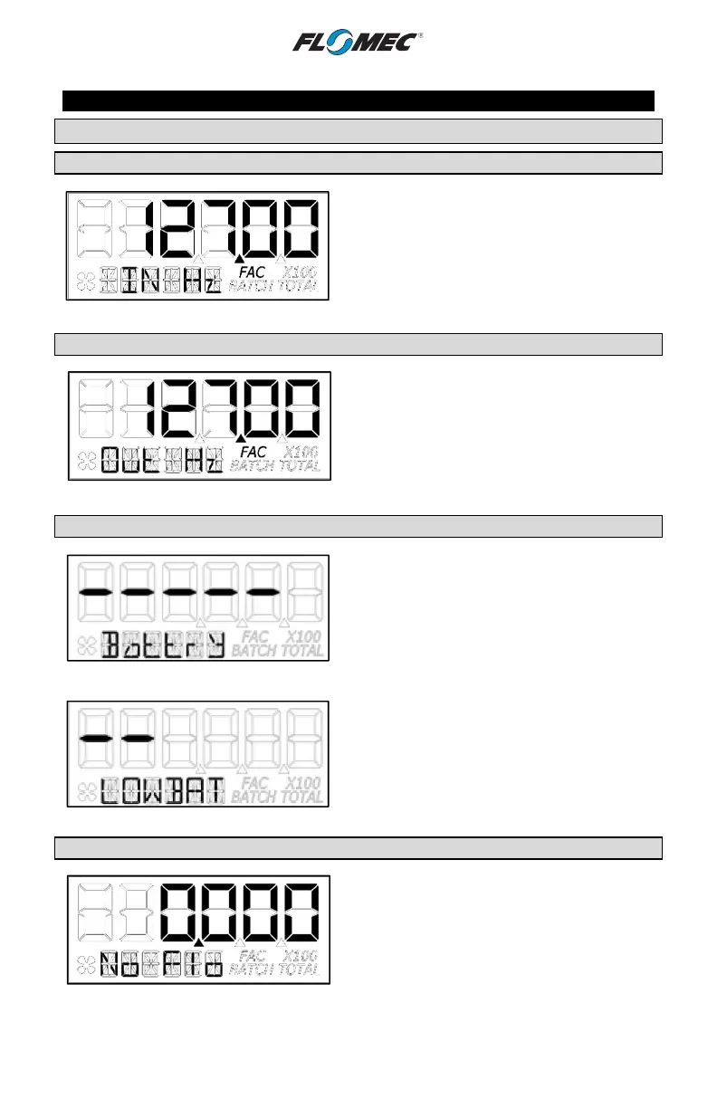
Screen 1 – Input Frequency
After the button is released, the software will
advance and display the input frequency in Hz.
The top row is used to indicate frequency. The
information row will display messages. (See
Figure 11-2)
Figure 11-2
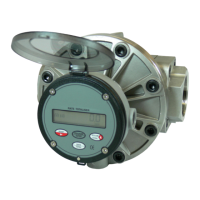
Screen 2 – Output Frequency
Advancing to next screen will display the output
frequency in Hz.
The top row is used to indicate frequency. The
information row will display messages. (See
Figure 11-3)
Figure 11-3
Screen 3 – Battery Status
Advancing to the next screen will display the
battery status.
The top row is used to indicate battery life with
each dash indicating a percentage of battery life
remaining. The information row will display
messages. (See Figure 11-4)
Figure 11-4
NOTE: If the battery life is sufficiently low,
“LOWBAT” will be displayed in the information
row. This low battery message will be displayed
automatically without running a diagnostic battery
check. (See Figure 11-5)
Figure 11-5
Screen 4 – Flow Status
Advancing to the next screen will display the flow
status.
The top row is used to indicate flow rate in the
volume units programmed into the computer.
The information row will display messages, i.e.:
No Flo, Lo Flo, or Hi Flo. (See Figure 11-6)
Figure 11-6