10
INSTALLATION
PRODUCT DESCRIPTION
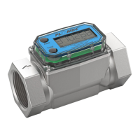
This computer electronics is designed specifically for use on FLOMEC® Turbine Housings.
It is also designed to work with several accessory output modules.
The CMOS, microprocessor-based electronics have extremely low power requirements and
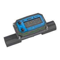
data retention capabilities in both RAM and ROM. Information is clearly displayed on a large
6-digit LCD readout with three-point floating decimal for totals from .001 to 999,999 (x1),
9,999,990 (x10), or 99,999,900 (x100). All operations are easily accessed with the two
buttons on the front panel.
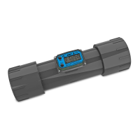
In a FLOMEC turbine meter, liquid flows through the turbine housing causing an internal rotor
to spin. As the rotor spins, an electrical signal is generated in the pickup coil. This pulse data
from the turbine is translated into calibrated flow units shown on the computer's display
readout.
INSTALLATION
Before installation, ensure your computer model meets your specific needs. Refer to the
Specifications Section to confirm required features. The model number of your computer is
displayed on the outside wall of the computer housing and also inside the computer housing
on the floor of the battery holder.
If you ordered your computer electronics with a turbine body, the electronics are installed at
the factory.
If you ordered your computer separately as a replacement, simply plug in the pickup coil
connector and mount the computer on your turbine body with the four screws at the corners
of the faceplate. Make sure the seal is fully seated before tightening the screws.
If you ordered the computer with a turbine body and an accessory module, please review
and thoroughly understand all installation instructions before proceeding.
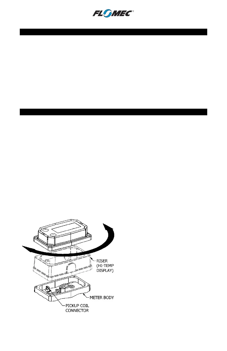
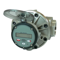
All FLOMEC turbine meters are designed to measure flow in only one direction. The direction
is indicated by the arrow on the turbine outlet port. If the computer display is upside down in
your installation, remove the four corner screws, turn the display 180 degrees and reinstall
the screws. (See Figure 4-Screws not shown.)
NOTE: When rotating the computer
display, it is not necessary to disconnect
the pickup coil connector; however, care
should be taken to avoid inadvertent strain
on the connector wires.
Hi-Temp Displays have a riser located
between the meter body and the display.
(Shown in phantom lines in Figure 4.)
Figure 4