8
5. Function
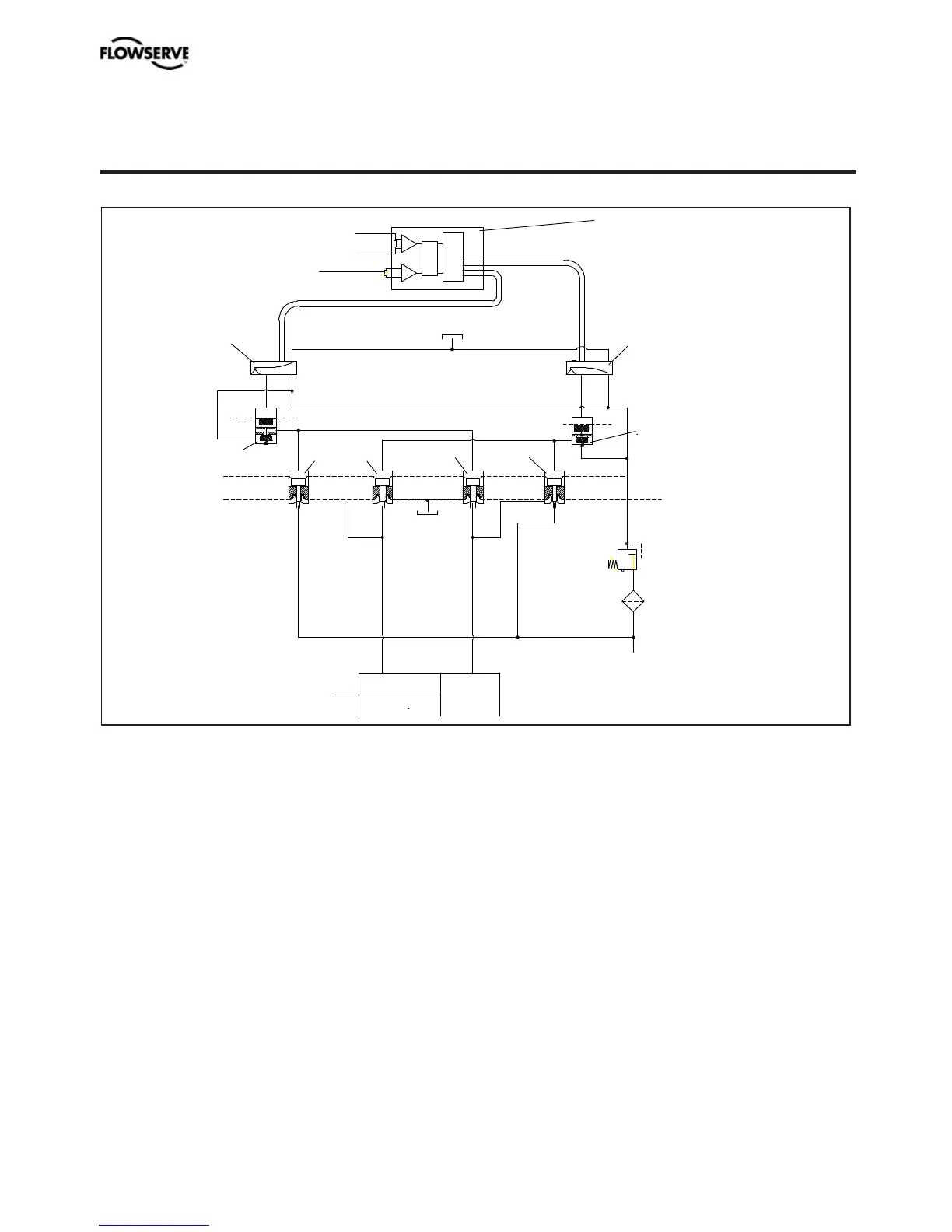
The control signal function and the feedback
from the potentiometer position are converted
to digital signals that are processed with a PID
algorithm in the microprocessor. This provi-
des control signals to the two piezo-valves.
Valves B and E deliver air to the actuator while
valves C and F exhaust air from the actuator
to atmosphere. Valves B and C are controlled
by Piezo-valve 1 and valve A. Valves E and F
are controlled by Piezo-Valve 2 and valve D.
Full supply pressure is directed to valves B
and E. Air with filtered and reduced pressure
is supplied to valves A, C, D and F.
For double acting actuators, connect C+ and
C- to the actuator.
C-
Venting
Air supply 2 - 6 bar (29-87 psi)
Pressure
regulator
Piezo-valve 1
Piezo-valve 2
Control signal 4 - 20 mA
Potentiometer
D
E
C
F
B
A
1.2 bar (17.4 psi)
Replacable
Filter
Actuator
Diaphragm
C+
Venting
Signal converter
and
microprocessor
For single acting (spring return) actuators
connect C+ to the actuator and plug port
C-. Single acting versions have the air block
plugged in one end as default. To convert from
double to single acting function - see page 11.
Increasing input signal changes position in
piezo-valve 1, causing valve A to close.
Supply pressure is then allowed to open valve
B and flow to the actuator via the C+ port.
When the actuator reaches its new steady
state position piezo-valve 1 closes which
causes valves B and C to close shutting off
supply air to the actuator.
A decreasing input signal functions in the
same manner, except uses piezo-valve 2 and
valves D, E and F.
2 - 7 bar (30 - 105 psi)
Internal pilot valve A
Internal pilot valve D
PMV D3 Digital Positioner FCD PMENIM0001-06 A5 09/16