13
Warning! In a hazardous
environment where there is
a risk of explosion, electrical
connections must comply with
the relevant regulations.
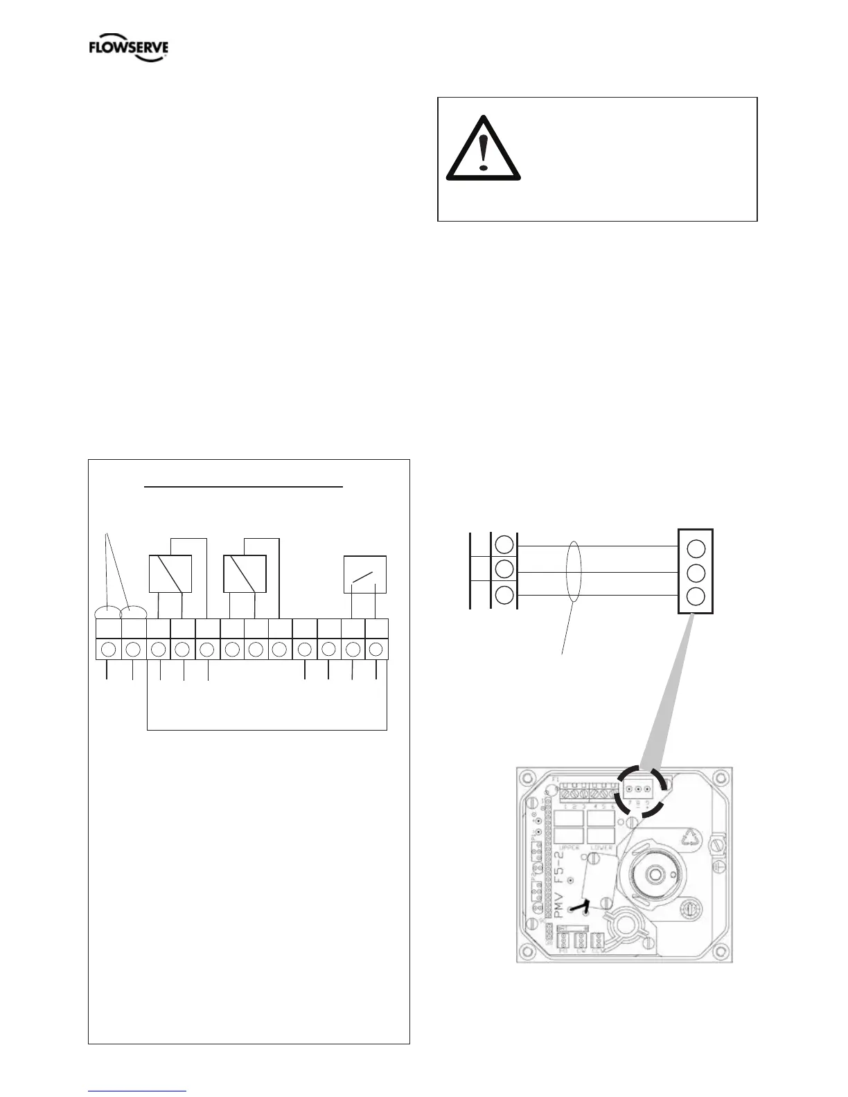
Electrical connections
Terminal block diagram for the PMV D3 and
PMV D3 Ex.
PMV D3
The terminal block (below) for the positioner
is accessible when the aluminum cover and
inner cover are removed, see Section 8.
Remote unit
The remote unit shall be connected between
terminals 3, 4 and 5 in the PMV D3 and 7, 8
and 9 in the remote unit. Use a shielded cable
and ground it to the PMV D3 or to the remote
unit. (Not both units at the same time.)
Max distance between PMV D3 and remote
unit: 5m (16.4 ft).
When installing the PMV D3 Intrinsically
safe unit - always consider control drawing
3-86 found at www.pmv.nu/downloads.
1 Input signal + 4-20 mA ,
Hart, Profibus PA, Foundation Fieldbus
2 Input signal – 4-20 mA ,
Hart, Profibus PA, Foundation Fieldbus
3 Switch 1 NO/Remote
4 Switch 1 NC/Remote
5 Switch 1 COM/Remote
6 Switch 2 NO
7 Switch 2 NC
8 Switch 2 COM
9 4-20 mA + Feedback, 11-28 V DC
10 4-20 mA – Feedback, 11-28 V DC
11 Alarm output +, 8-28 V DC
12 Alarm output –, 8-28 V DC
PMV D3, 12 terminals
Option
Connection
Connecting a remote unit
+ – + – + –
Remote unit
1 2 3 4 5 6 7 8 9 10 11 12
Optional
PMV D3/D3Ex Remote unit
3
4
5
7
8
9
Shielded cables,
grounded on
the PMV D3.
7 8 9