14
PMV D3 Ex
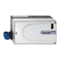
The terminal (below) for the positioner is
accessible when the terminal cover is remo-
ved, see Section 8.
Warning! In a hazardous
environment where there is
a risk of explosion, electrical
connections must comply with
the relevant regulations.
For more data with electrical ratings and
barrier values - please download control
drawing cdwg 3-86 from www.pmv.nu/
downloads
1 Input signal + 4-20 mA ,
Hart, Profibus PA, Foundation Fieldbus
2 Input signal – 4-20 mA ,
Hart, Profibus PA, Foundation Fieldbus
3 Remote unit
4 Remote unit
5 Remote unit
9 4-20 mA + Feedback, 11-28 V DC
10 4-20 mA – Feedback, 11-28 V DC
11 Alarm output +, 8-28 V DC
12 Alarm output –, 8-28 V DC
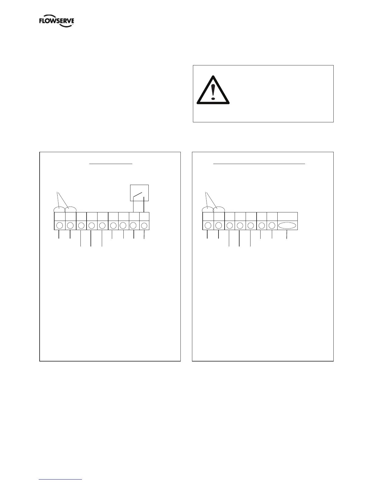
1 Input signal +24V Profibus DP
2 Input signal -24V Profibus DP
3 Remote unit
4 Remote unit
5 Remote unit
-P Profibus DP Communication
-N Profibus DP Communication
DGND Digital Ground
Optional
Optional
PMV D3 Ex PMV D3 Ex Profibus DP
Connection Connection
+ – + – + – + –
1 2 3 4 5 9
10 11 12
+ - 3 4 5 -P
-N DGND
Remote unit Remote unit