38
Transmitter boards
The equipment for transmitter feedback
consists of a circuit board A, cam assembly
B and screws.
General PCB versions:
- with mechanical switches, SPDT
- with NAMUR sensors, DIN 19234
- with proximity switches
- with feedback transmitter and/or remote only
A
B
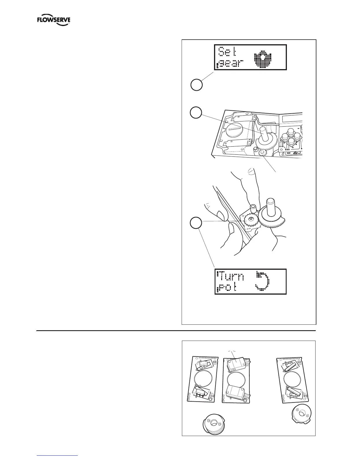
K
Potentiometer
90° and 270° spring loaded potentiometer
The spring-loaded potentiometer K can be
removed from the gearwheel for calibration
or replacement.
If the potentiometer is replaced or the setting
is changed, it must be calibrated.
• Select the menu Calibrate - Expert - Cal pot.
The display shows Set gear (1).
• Turn the spindle shaft (2) clockwise to
end position and press OK. Turn counter
clockwise to the end and press OK.
• Unmesh the potentiometer (3) and turn
it according to display until OK is shown.
Press OK.
• Re-align spring on potentiometer to secure
it.
1
2
3