39
B
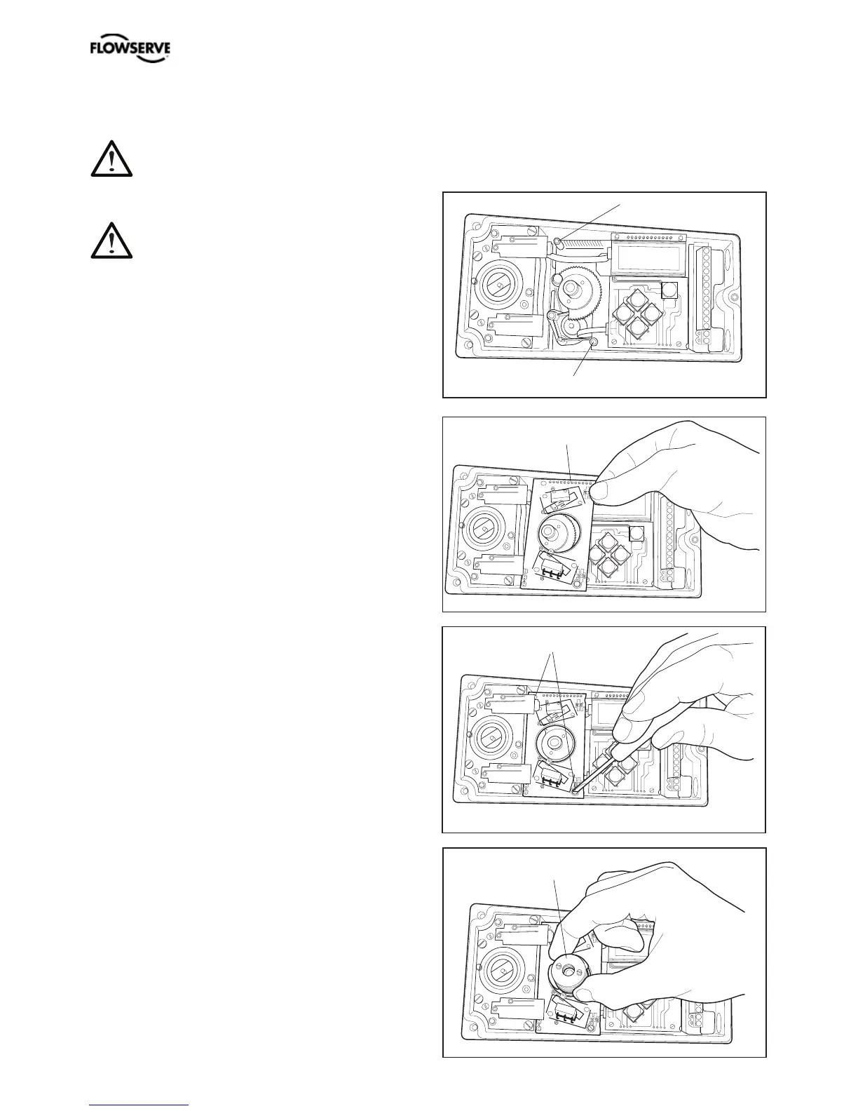
Transmitter board installation
Maintenance and repairs on PMV
D3 units with hazardous area
approvals should only be made
by authorized staff.
• Remove the cover, indicator and inner
cover according to the description on page
37.
• Check that both spacers C are installed.
• Carefully mount the PCB in its position. The
pins D should fit in the connector and the
positioner’s motherboard. Make sure that
the feedback PCB is properly connected.
• Secure the PCB with the enclosed screws
E.
• Install the cam asssembly B on the shaft
and push it down to its position. If the
board has microswitches, be careful not
to damage the levers.
E
D
C
C
Caution! Turn off the power and air supply before starting the installation.