xi
Figures
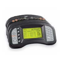
Figure 1 1560 Black Stack Thermometer with Two Modules Attached . . . . . . 5
Figure 2 System Diagram . . . . . . . . . . . . . . . . . . . . . . . . . . . . . . 8
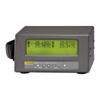
Figure 3 Typical Display . . . . . . . . . . . . . . . . . . . . . . . . . . . . . . 9
Figure 4 Typical graph mode display . . . . . . . . . . . . . . . . . . . . . . . 10
Figure 5 Data Flow . . . . . . . . . . . . . . . . . . . . . . . . . . . . . . . . 15
Figure 6 Attaching new modules . . . . . . . . . . . . . . . . . . . . . . . . . 21
Figure 7 Channel numbering . . . . . . . . . . . . . . . . . . . . . . . . . . . 24
Figure 8 Typical Statistical Display . . . . . . . . . . . . . . . . . . . . . . . . 46
Figure 9 Typical Graph Window Display . . . . . . . . . . . . . . . . . . . . . 49
Figure 10 Typical Scrolling Display . . . . . . . . . . . . . . . . . . . . . . . . 50
Figure 11 RS-232 Cable Wiring . . . . . . . . . . . . . . . . . . . . . . . . . . 63
Figure 12 Programming Example . . . . . . . . . . . . . . . . . . . . . . . . . 111
Figure 13 Sensor Wiring Diagram. . . . . . . . . . . . . . . . . . . . . . . . . 114
Figure 14 Sensor Wiring Diagram. . . . . . . . . . . . . . . . . . . . . . . . . 120
Figure 15 PRT Scanner Module Sensor Wiring Detail . . . . . . . . . . . . . . 126
Figure 16 Sensor Wiring Diagram. . . . . . . . . . . . . . . . . . . . . . . . . 134
Figure 17 Thermistor Scanner Module Sensor Wiring Detail . . . . . . . . . . . 141
Figure 18 2565 Module Thermocouple Receptacle Operation . . . . . . . . . . 150