8.4 Calibration
This section explains the calibration procedure for the 2561 HTPRT Module.
8.4.1 Calibration Parameters
The resistance measurement is derived from the ratio between the voltage mea
-
surements of the input resistor and the internal reference resistor (10Ω)using
the following equation.
resistance ADJ ratio ADJ ratio=+ + −(. _ ) _ (. )10 0 1 0
10 0
Two adjustable calibration parameters are used for calibration: 0_ADJ and
10_ADJ. 0_ADJ directly affects the measurement at 0Ω. It has negligible effect
at 10Ω. 10_ADJ directly affects the measurement at 10Ω. It has negligible ef
-
fect at 0Ω. Each of the parameters has a positive effect at their primary
resistances: increasing the value of the parameter increases the measured resis
-
tance. The default and theoretically normal value for each is 0.
8.4.2 Front-panel Access
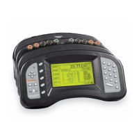
The calibration parameters 0_ADJ,and10_ADJ can be adjusted to optimize the
accuracy. They can be accessed from the front panel of the 1560 using the CAL
DEVICE soft-key function. This is found in the MODULE sub-menu.
Pressing the CAL DEVICE soft-key shows a list of devices with the module
position number. Use the UD buttons to move the cursor to the HTPRT mod-
ule and press ENTER.
SELECT A DEVICE TO CALIBRATE
>HPRT 1
TCS 2
PRTS 3
After the device is selected a new window appears showing the parameters and
functions available from the device. New values can be entered for the parame
-
ters using the numeric buttons and pressing ENTER.TheUD buttons can be
used to move between parameters.
1560 Thermometer Readout
User’s Guide
122

 Loading...