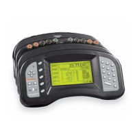
SELECT A DEVICE TO CALIBRATE
>SPRT 1
TCS 2
PRTS 3
After the device is selected a new window appears showing the parameters and
functions available from the device. New values can be entered for the parame
-
ters using the numeric buttons and pressing ENTER.TheUD buttons can be
used to move between parameters.
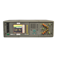
CALIBRATE DEVICE: SPRT
0 ADJ: 0.0
100 ADJ: 0.0
400 ADJ: 0.0
CAL DATE: 05-21-96
SER NUM: A26123
For the 2560/2567 SPRT module the list of parameters includes 0_ADJ,
100_ADJ,and400_ADJ as described above. The list also includes the calibra
-
tion date (CAL DATE) parameter, used to record the date the module was cali
-
brated, and the (SER NUM) parameter, used to record the serial number of the
module.
7.4.3 Calibration Procedure (2560)
Calibration requires adjustment of the 0_ADJ, 100_ADJ,and400_ADJ parame
-
ters at three specific input resistances. If the resistances used are approximately
0Ω, 100Ω and 400Ω respectively the adjustments are independent and the pro
-
cedure is simple. The order in which the adjustments are performed is impor
-
tant. The adjustment of the 400_ADJ parameter must be performed last as the
adjustments of 0_ADJ and 100_ADJ affect the measurement at 400Ω but
400_ADJ does not affect the measurements at 0Ω and 100Ω. Either channel
can be used for calibration. Set the conversion type to R(Ω)todisplayresis
-
tance (see Section 5.2.1.1 ). The accuracy required of the resistance standards is
1/4 of the instrument accuracy: that is ±0.00012Ω at 0Ω, ±0.0005Ω (5 ppm) at
100Ω, and ±0.002Ω (5 ppm) at 400Ω. The recommended procedure is as
follows:
117
7 2560/2567 SPRT Module
Calibration