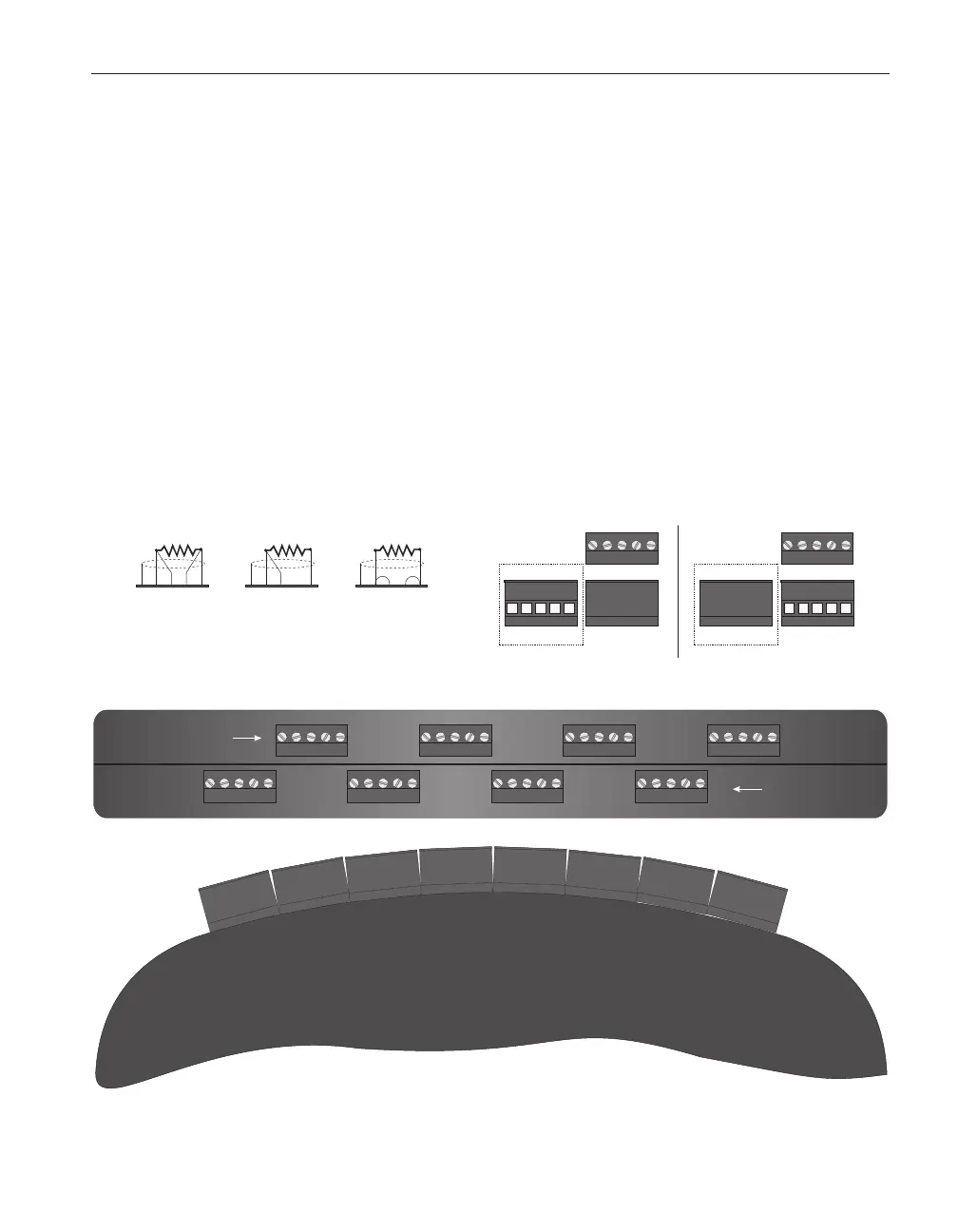
Three-wire sensors are connected as shown in Figure 17. The shield, if used, is
connected to pin 1 on the left. One pair of wires connects to pins 2 and 3. The
opposite wire connects to pin 5. Pin 4 is left unconnected. Pins 2 and 5 source
current. The potential is also sensed at pins 2 and 5 while the potential at pin 3
is used to compensate for the lead resistance of wires 2 and 5. Be sure to check
that the wiring configuration for that row is set to 3 as explained above!
Two-wire sensors are connected as shown in Figure 17. The shield, if used, is
connected to pin 1 on the left. One wire connects both pins 2 and 3. The oppo
-
site wire connects to both pins 4 and 5. Be sure to check that the wiring config
-
uration for that row is set to 4 as explained above! When using two-wire
sensors the 2564 is unable to compensate for lead resistance.
11.3.3 Setting Coefficients
Once a thermistor is properly connected to the 2564, the 1560 can read out its
resistance. To display temperature accurately the 1560 must be programmed
with the characterization coefficients for the sensor. This is done using the
141
11 2564 Thermistor Scanner Module
Operation
THERMISTOR
SCANNER
MODULE
2564
Front Row
Rear Row
111222
333
444
555
4-Wire 3-Wire 2-Wire
Wiring Detail
Back Front
Top
1122
33
44
55
Connector Detail
Back Front
Top
1122
33
44
55
Sensor wire holes
facing back of module
Sensor wire holes
facing front of module
Figure 17 Thermistor Scanner Module Sensor Wiring Detail