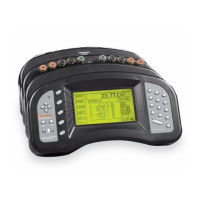
Below are some examples of using the device commands to set the device setup
parameters. For these examples it is assumed that the 2560/2567 SPRT Module
is placed first in the stack. These commands can be sent through any communi
-
cation interface including the IEEE-488 and RS-232 interfaces.
SYST: MOD1:DEV1:WRIT "CURR",1.4 Set the excitation current to 1.4
mA.
SYST:MOD1:DEV1:READ? "CURR" Read the excitation current.
7.4 Calibration
This section explains the calibration procedure for the 2560/2567 SPRT
Module.
7.4.1 Calibration Parameters
The resistance measurement is derived from the ratio between the voltage mea
-
surements of the input resistor and reference resistor (100Ω) using the follow
-
ing equation.
resistance ADJ ratio=⋅ −+
−
[. ( )( ) .][(
.
8 3333 10 10 1 0
4
400_
100 0 1 0.) (.)]++−
100_ 0_
ADJ ratio ADJ ratio
Three adjustable calibration parameters are used for calibration: 0_ADJ,
100_ADJ,and400_ADJ. 0_ADJ directly affects the measurement at 0Ω.Ithas
negligible effect at 100Ω but significant affect at higher resistances. 100_ADJ
directly affects the measurement at 100Ω. It has negligible effect at 0Ω and
proportionately greater effect the higher the resistance. 400_ADJ directly af-
fects the measurement at 400Ω. It has negligible effect at 0Ω and 100Ω with
greater effect the more the resistance deviates from 0Ω or 100Ω. Each of the
parameters has a positive effect at their primary resistances: increasing the
value of the parameter increases the measured resistance. The default and theo
-
retically normal value for each is 0.
7.4.2 Front-panel Access
The calibration parameters 0_ADJ, 100_ADJ,and400_ADJ can be adjusted to
optimize the accuracy. They can be accessed from the front panel of the 1560
using the CAL DEVICE soft-key function. This is found in the MODULE
sub-menu. Pressing the CAL DEVICE soft-key shows a list of devices with
the module position number. Use the UD buttons to move the cursor to the
SPRT module and press ENTER.
1560 Thermometer Readout
User’s Guide
116

 Loading...