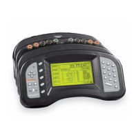
13.4.2 Front-Panel Access
The calibration parameters can be accessed from the front panel of the 1560 us
-
ing the CAL DEVICE function in the MODULE soft-key menu (see Section
5.4.3). Select the TCS device. A window appears showing the calibration pa
-
rameters for the device. The calibration parameters appear in two screens. The
two screens appear alternately each time the device calibration window ap
-
pears. The first screen contains the first nine parameters—AMP GA through CJ
OS 6.
159
13 2566 Thermocouple Scanner Module
Calibration
Parameter Description
AMP GA Set to the nominal gain of the amplifier, type 1 or 2
OS 1 Adjusts the voltage accuracy of Inputs 1–6 at 0 mV
GA 1 Adjusts the voltage accuracy of Inputs 1–6 at 100 mV
CJ OS 1 Adjusts the internal CJC accuracy of Input 1
CJ OS 2 Adjusts the internal CJC accuracy of Input 2
CJ OS 3 Adjusts the internal CJC accuracy of Input 3
CJ OS 4 Adjusts the internal CJC accuracy of Input 4
CJ OS 5 Adjusts the internal CJC accuracy of Input 5
CJ OS 6 Adjusts the internal CJC accuracy of Input 6
OS 2 Adjusts the voltage accuracy of Inputs 7–12 at 0 mV
GA 2 Adjusts the voltage accuracy of Inputs 7–12 at 100 mV
CJ OS 7 Adjusts the voltage accuracy of Input 7
CJ OS 8 Adjusts the voltage accuracy of Input 8
CJ OS 9 Adjusts the voltage accuracy of Input 9
CJ OS 10 Adjusts the voltage accuracy of Input 10
CJ OS 11 Adjusts the voltage accuracy of Input 11
CJ OS 12 Adjusts the voltage accuracy of Input 12
CAL DATE Records the date the module was calibrated
Table 29 Themocouple Scanner Module calibration parameters