5100 Series
Table
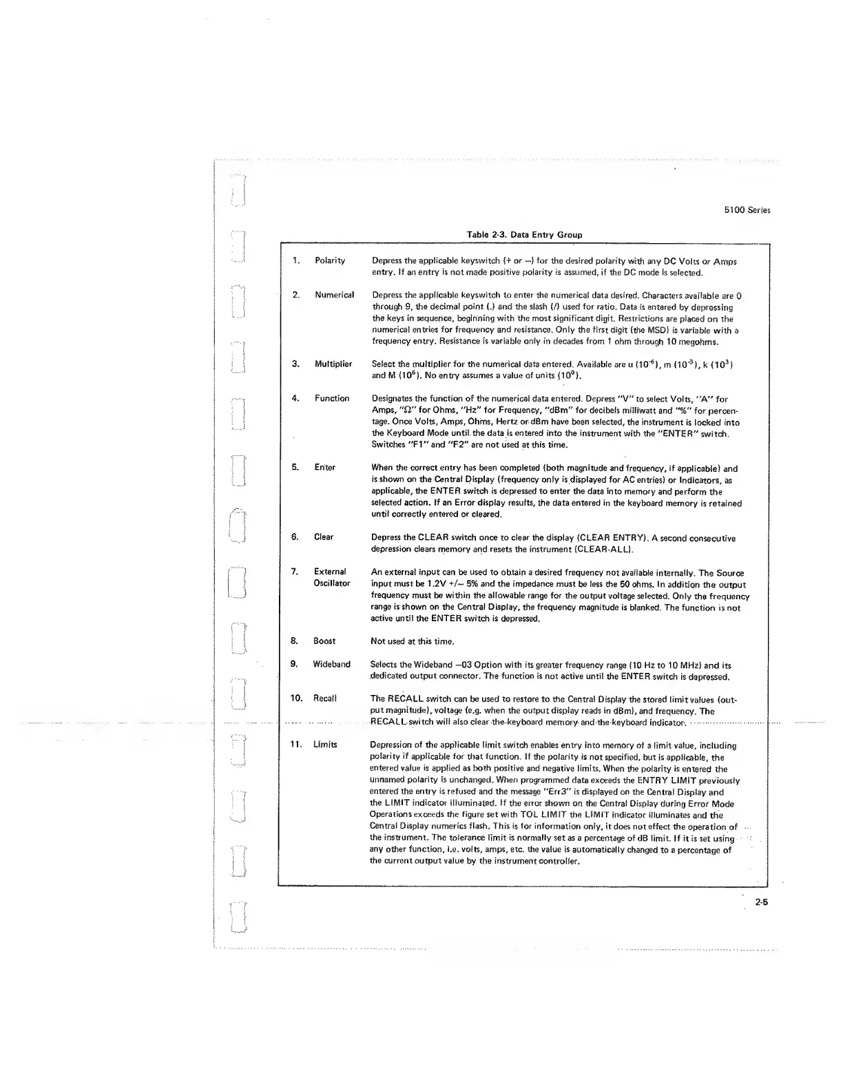
2-3.
Data Entry
Group
1. Polarity Depress
the
applicable
keyswitch
(+ or
—
)
for
the
desired
polarity
with any
DC Volts or
Amps
entry. If
an
entry
is
not
made
positive polarity is assumed,
if the DC mode is
selected.
2. Numerical Depress the applicable keyswitch
to
enter the
numerical
data
desired.
Characters
available are
0
through
9,
the
decimal point
(.)
and the
slash
(!)
used
for
ratio.
Data is
entered
by depressing
the keys
in
sequence,
beginning
with the most significant digit.
Restrictions are
placed
on the
numerical
entries
for
frequency
and
resistance.
Only the first digit
(the MSD) is
variable with
a
frequency
entry. Resistance is variable only in decades
from 1
ohm through 10
megohms.
3.
Multiplier
Select the multiplier for the numerical
data entered. Available
are u
(10'
6
),
m
(10"
3
),
k
(10
3
)
and M
(10
6
),
No entry assumes
a
value of units
(10°).
4. Function Designates
the
function of
the
numerical
data
entered.
Depress "V"
to select
Volts, "A" for
Amps, “SI"
for
Ohms,
“Hz" for Frequency,
"dBm" for decibels
milliwatt
and
"%"
for
percen-
tage. Once Volts, Amps, Ohms, Hertz or dBm have
been selected,
the instrument
is
locked into
the Keyboard Mode until the data is entered into
the instrument
with the
"ENTER"
switch.
Switches "FI" and "F2"
are
not used
at
this time.
5. Enter
When
the
correct entry
has been completed (both
magnitude
and frequency, if
applicable) and
is shown on the Central Display
(frequency
only
is displayed
for AC
entries! or
Indicators,
as
applicable,
the
ENTER
switch is
depressed
to enter the
data into memory
and
perform
the
selected action. If an Error display results,
the
data
entered in
the keyboard
memory is retained
until
correctly entered
or cleared.
6.
Clear
Depress
the CLEAR switch once
to
clear
the display
(CLEAR
ENTRY).
A second
consecutive
depression clears
memory
and
resets
the instrument
(CLEAR-ALU.
7.
External
An external input can be used to
obtain
a
desired frequency
not
available
internally.
The
Source
Oscillator
input must
be
1
,2V
+/—
5% and the impedance must
be
less
the 50 ohms,
in
addition
the output
frequency
must be
within
the allowable range for
the output voltage
selected.
Only
the
frequency
range
is shown on the Central Display,
the
frequency
magnitude is
blanked. The
function is not
active until
the
ENTER
switch
is
depressed.
8. Boost
Not
used at
this
time.
9.
Wideband Selects
the
Wideband
--03
Option with its
greater frequency
range
(10
Hz to
10
MHz)
and
its
dedicated output connector.
The function
is not active until
the
ENTER
switch is
depressed.
10. Recall
The RECALL
switch
can be used to restore to the
Central
Display the stored limit
values (out-
put
magnitude),
voltage (e.g. when the output display
reads in
dBm), and frequency.
The
RECALL switch
will also dear the keyboard
memory and the keyboard
indicator.
11.
Limits
Depression of the applicable limit
switch
enables
entry
into memory
of
a
limit value,
including
polarity
if
applicable
for
that
function.
If the polarity is
not specified, but
is applicable,
the
entered
value
is
applied as both positive
and negative limits.
When
the polarity
is
entered the
unnamed polarity is
unchanged.
When
programmed
data exceeds
the ENTRY LIMIT
previously
entered
the
entry is
refused and the message "Err3"
is displayed
on the
Central
Display and
the
LIMIT indicator
illuminated. If
the
error
shown
on the Central
Display
during Error
Mode
Operations exceeds
the figure
set with TOL LIMIT die LIMIT
indicator illuminates
and the
Central
Display numerics flash. This
is
for
information
only, it
does not effect
the
operation of
the instrument. The
tolerance limit is normally
set as a
percentage of
dB limit, if
it
is set using
any
other function, i.e.
volts, amps, etc. the value is
automatically
changed
to a percentage
of
the current output value
by
the Instrument controller.
 Loading...


