5100 Series
NOTE
(a.)
Some VOM's have
a
non-linear input
impedance; i.e.,
a
meter
with
10
kCij volt input
impedance might have the
positive
half
cycle
at
10
kClj V
and
the negative
half
cycle at
5 kfl!
V
or the positive at 10 kTlj V and the
negative at 20 kflj V, resulting in
measure-
ment inaccuracies. This type
of
VOM
can
be
calibrated by either using the
optional wide-
band output (up to 3. 1623
V)
or by
connecting
a resistor in parallel
with
the
VOM input
(across the 5100 Series output
terminals).
Use
the
following formula
to
compute the resis-
tance value, then select the next higher
standard resistor value.
Rc
=
EP/IL where:
Rc
~
Computed Resistance
Ep
—
Programmed
Calibrator output
II
—
Maximum Load
current
for
pro-
grammed
calibrator range (see specifica-
tions)
(b.) Wideband AC
Voltmeters
(bandwidihs
exceeding
1
MHz) are
susceptable
to high-
frequency
noise
on the
low ranges and should
be calibrated at
levels below
10 m V
using the
Wideband
(10
Hz
-
10
MHz) Output (Option
-
03).
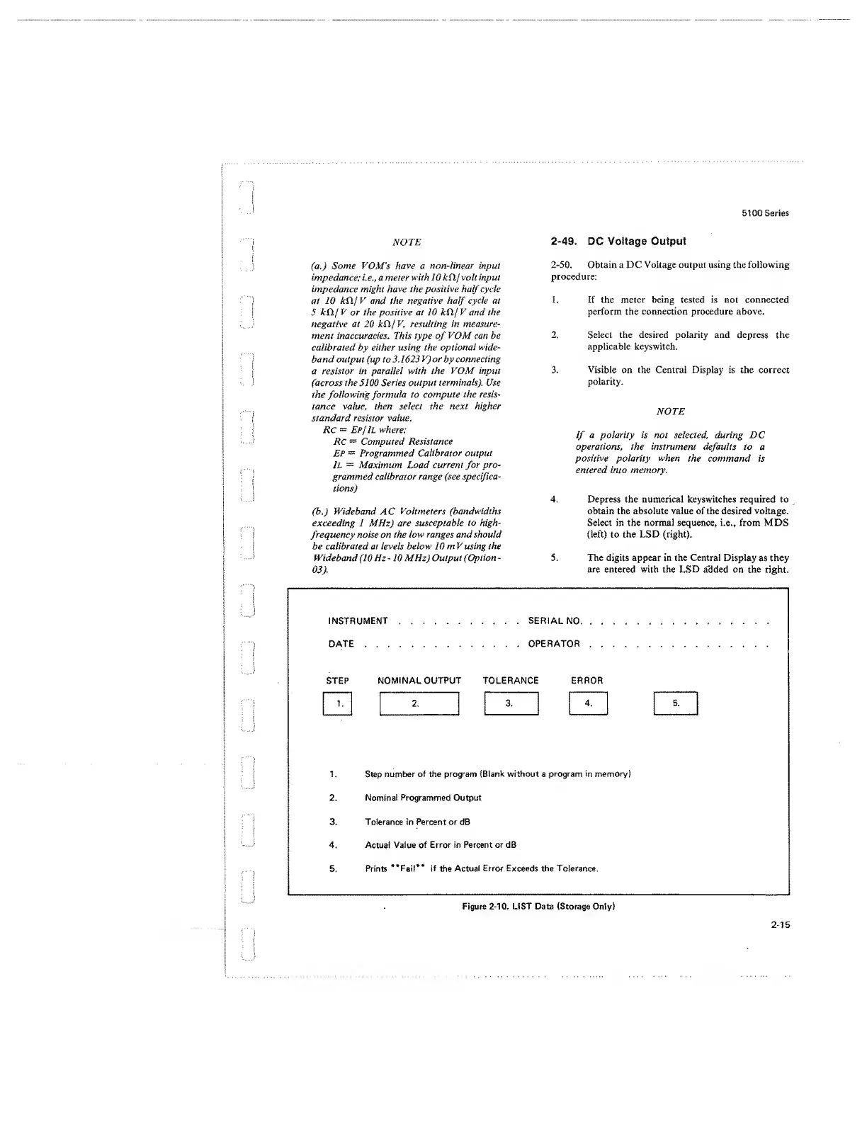
INSTRUMENT
SERIAL
NO.
DATE OPERATOR
STEP
NOMINAL OUTPUT TOLERANCE ERROR
1 . 2. 3.
4,
5.
1.
Step
number of the program
(Blank
without a
program in memory)
2.
Nominal Programmed Output
3. Tolerance in Percent or dB
4. Actual
Value of
Error in Percent or dB
5.
Prints
“Fail** if
the
Actual
Error
Exceeds the Tolerance,
Figure
2-10,
LIST Data (Storage Only)
2-49.
DC Voltage
Output
2-50.
Obtain a DC
Voltage output
using
the
following
procedure:
1. If the
meter
being
tested
is
not connected
perform the
connection
procedure above.
2. Select the desired polarity and
depress the
applicable keyswitch.
3. Visible
on the Central Display is the correct
polarity.
NOTE
If
a polarity is not selected, during
DC
operations, the instrument
defaults
to a
positive
polarity
when
the command is
entered into memory.
4. Depress the numerical keyswitches required to
obtain the absolute
value
of the desired voltage.
Select in the normal sequence,
i.e.,
from MDS
(left) to the LSD (right).
5. The digits appear
in
the Centra! Display
as
they
are entered
with
the LSD added on the
right.
2-15
 Loading...


