Operation
Summary of the Features
3
3-7
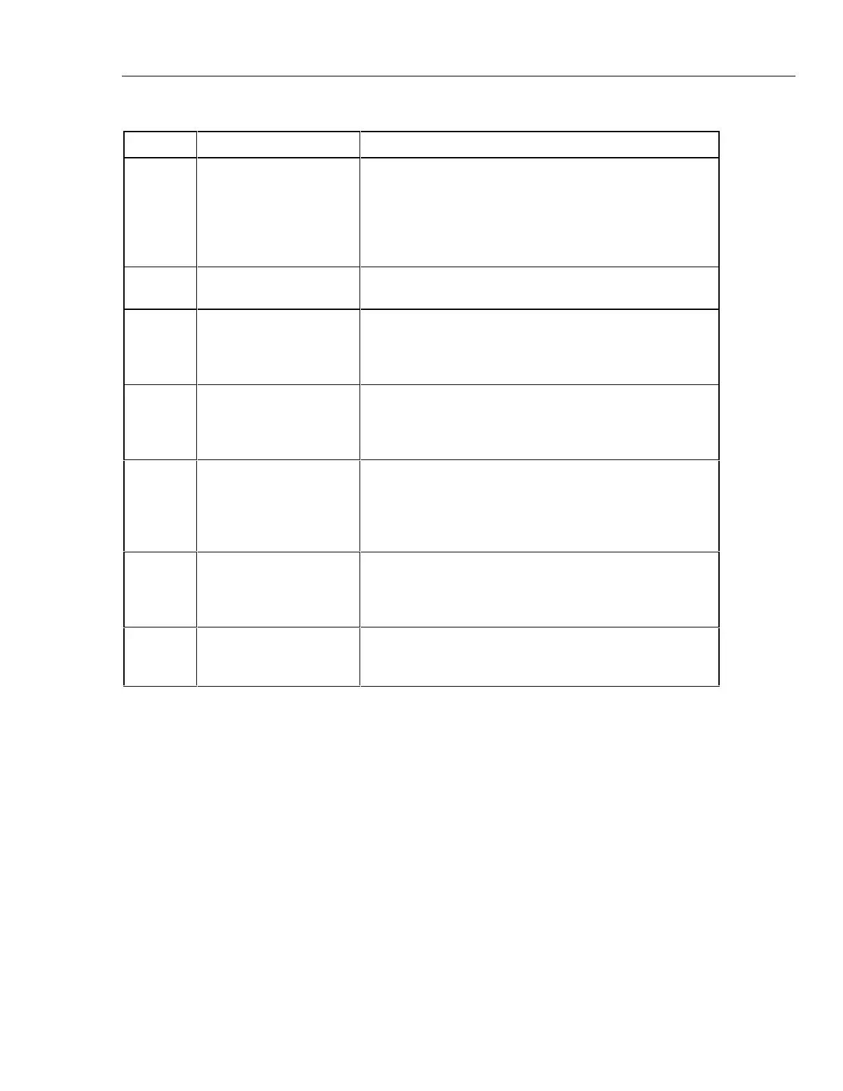
Table 3-2. 732B DC Standard Rear Panel Features
Item Feature Description
1 Recessed
CAL RESET
Switch
If the IN CAL indicator is off and normal 732B operating
conditions are met, pressing this momentary-contact switch for
approximately 4 seconds resets IN CAL. You should calibrate
the 732B before resetting the IN CAL indicator. Normally, a
calibration sticker covers the hole to prevent tampering with
this control.
2 BATTERY Swtich Connects and disconnects the battery from the charger and
reference circuitry.
3 MONITOR/EXT BAT IN
Connector
Provides the input/output point for three functions: (1)
powering the standard from external 12 to 15V dc. (2)
Measuring the resistance of the oven temperature thermistor.
(3) Remotely monitoring the IN CAL indicator state.
4 Fuse Type and Rating
Label
States the correct fuse type and rating for use in the 100, 120,
220, and 240V settings. Use of an improper fuse defeats the
safety design of the standard and can cause instrument
damage.
5 CHASSIS Connector A connection point for chassis ground. You can use this
connector to ground the chassis to the earth ground point in a
system of interconnected instruments. Another chassis
ground connection is on the front panel. (See the text in this
section for more information about guarding and grounding.)
6 Line Cord Plug and Fuse
Holder
Houses the ac line fuse and the male three-prong connector
for an IEC-type power cord. The plastic cover fits over the fuse
so it can be accessed only when the power cord is not
connected.
7 Line Voltage Selector Allows selection of four ac line voltage settings, 100, 120, 220,
and 240V, each with a tolerance of 10%. The accepted line
frequencies are 50 and 60 Hz.
www.valuetronics.com