Theory of Operation
Functional Description
4
4-11
DC
AC
Common
A
Inputs
to A/D
Converter
True RMS
AC
Converter
Current
Shunt
LO
HI
dx29f.eps
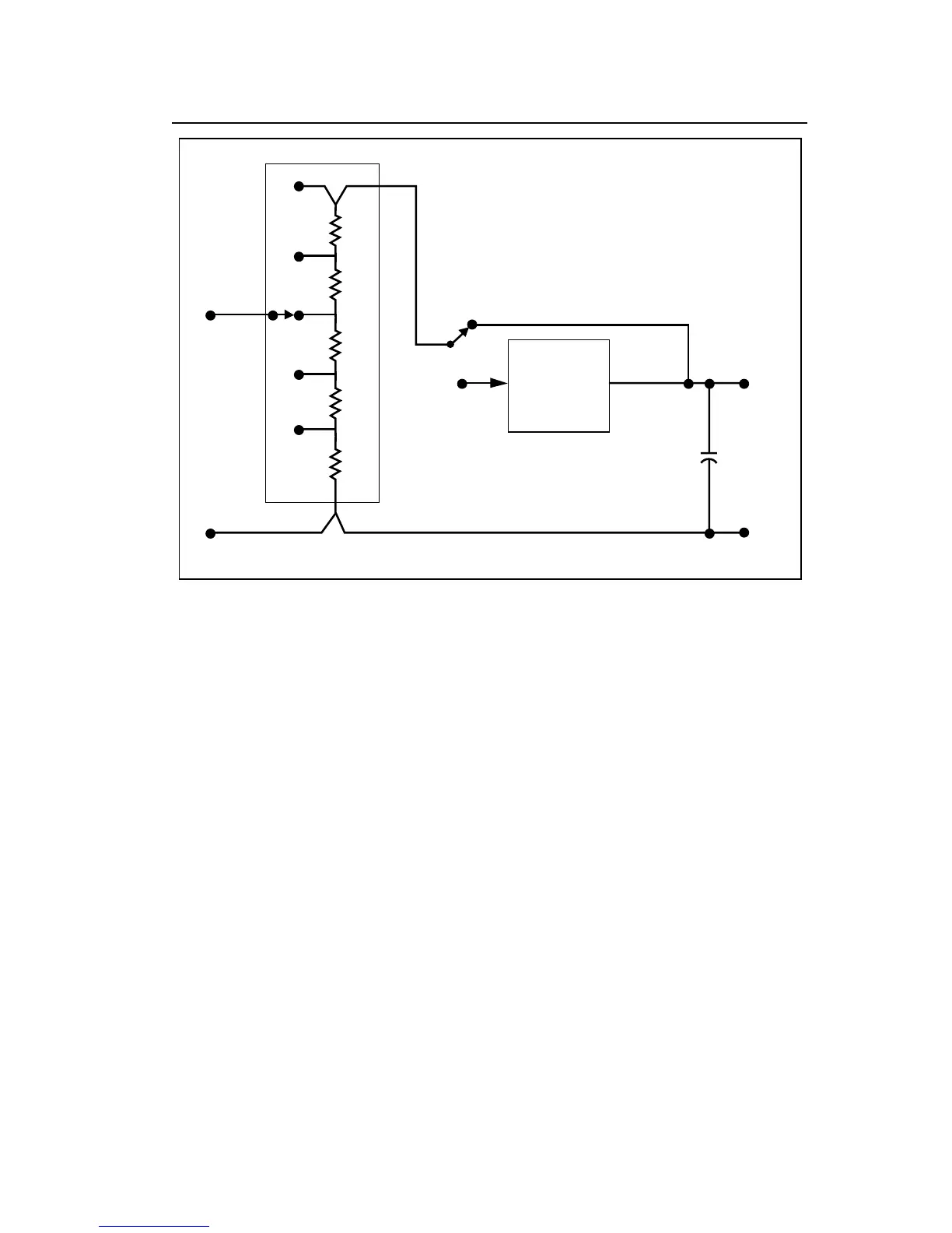
Figure 4-5. Current Measurement
The operation of the a/d converter during a resistance measurement is
basically as described earlier in this chapter, with a few exceptions. During
the integrate period the voltage drop across the unknown resistor charges the
INTEG capacitor. During the read period, the voltage across the known
resistor (stored on the flying capacitor) discharges the INTEG capacitor. The
length of the read period is a direct indication of the value of the unknown
resistor.
4-9. Conductance Measurement
Conductance measurements are made using a ratio technique similar to that
used in making resistance measurements as shown in Figure 4-6. The main
difference is that the function of the range and unknown resistors in the a/d
measurement cycle is reversed so that the smaller voltage is applied during
the integrate period, which minimizes error due to noise. During the integrate
period the voltage drop across the known resistor charges the INTEG
capacitor. During the read period the voltage drop across the unknown
resistor discharges the capacitor. Consequently the display presents a reading
that is the reciprocal of resistance, which is conductance.