Maintenance
Performance Tests
5
5-15
5-15. Resistance Test
Use the following procedure to verify proper operation of the resistance
function:
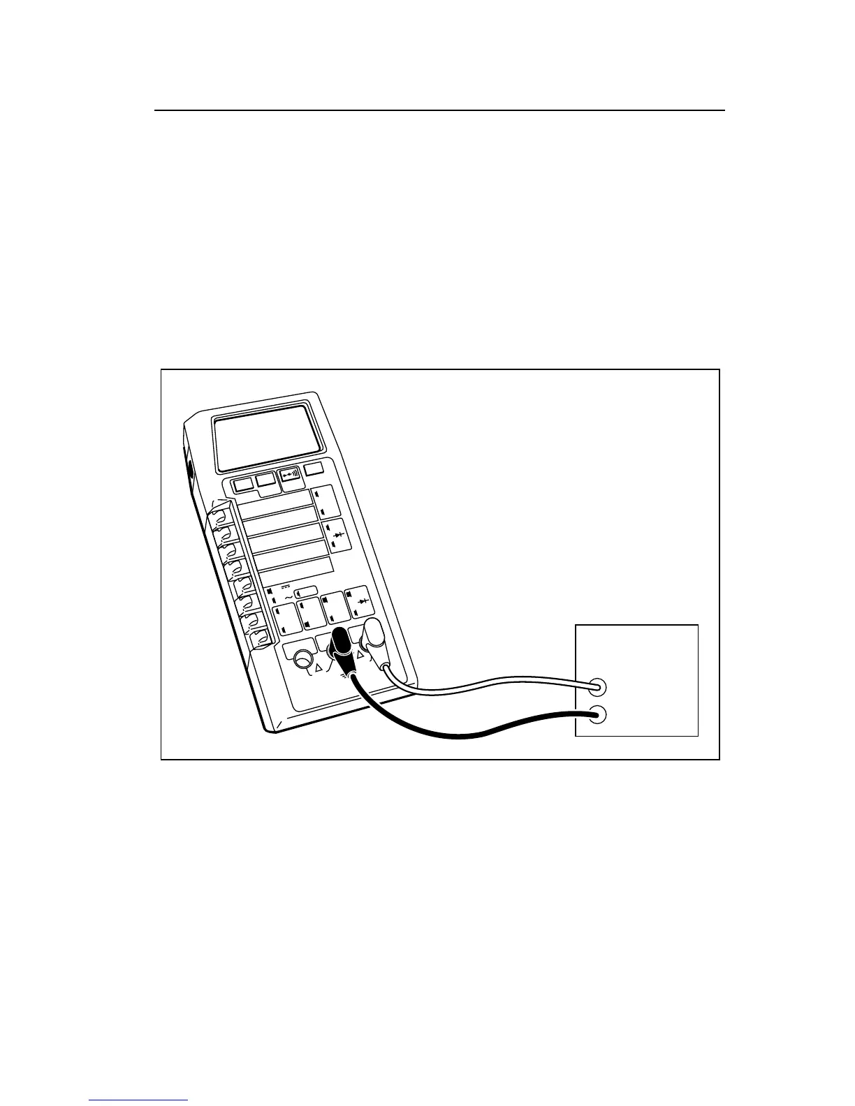
1. Connect the UUT and the DMM Calibrator as shown in Figure 5-4.
2. Select the resistance function and follow the steps 1 through 7 as listed
in Table 5-3. For each step, select the UUT function and range as
indicated. Program the DMM Calibrator for the specified input signal
and verify that the displayed UUT value is within the indicated limits.
2000mA
2000nS
A
A
COMMON
V Ω S
V
Ω
S
200mA
200
200k
200
µ
A
DC
AC
Hz
200mV
200
Ω
20mA
20
20k
2mA
2
2k
1000 DC
750 AC
M
Ω
Hz
dB
REL
1000V DC
750V AC
MAX
2A MAX
500V MAX
!
!
DMM
Calibrator
HI
UUT
LO
dx35f.eps
Figure 5-4. General Equipment Connection
Note
Most DMM Calibrators do not test resistance values beyond 10 M
Ω
To test the resistance function beyond 10 M
Ω
(optional steps 8 and
9 in Table 5-3), disconnect the DMM Calibrator and connect a
precision Reference Resistor for each value.