Operating the Meter from the Front Panel
Selecting a Function Modifier 3
3-17
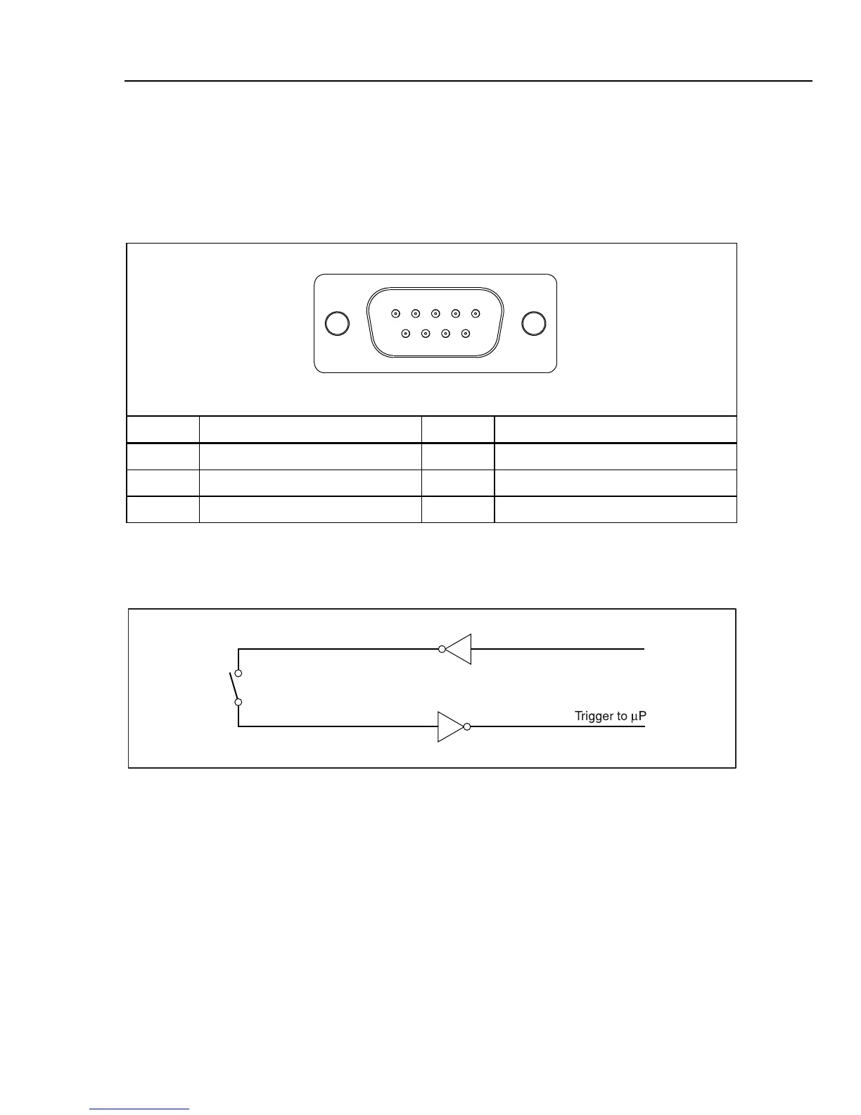
An external TTL signal on pin 9 will trigger a measurement cycle. Alternatively, pin 9 of
the RS-232 interface can be connected to pin 1 through an external switch. See Figure 3-
12. A measurement cycle is trigger when the switch is closed and the +5 volts from pin 1
is applied to pin 9. The trigger event occurs on the rising edge of the signal applied to
pin 9.
Table 3-4. RS-232 Pin Out
1234
678 9
5
eue23.eps
Pin # Description Pin # Description
1 +5 V OUT 2 RS-232 RXD
3 RS-232 TXD 5 RS-232 GND
6 Trigger Out 9 Trigger In
Figure 3-12 shows a method for using the +5 V OUT (pin 1) signal with an external
switch to trigger the Meter.
+5 V Out (Pin 1)
Trig In (Pin 9)
eue24.eps
Figure 3-12. External Trigger Circuit
Selecting a Function Modifier
This section describes the function modifiers available with the Meter. Function
modifiers are actions that the Meter performs on an input before a reading is displayed
(for example, a comparison to another value). Function modifiers can be used in
combination. See the “Using Function Modifiers in Combination” section later in this
chapter.
To use a function modifier, press a measurement function button to select that function,
and then press the function modifier button to modify that function. (For example, press
D to select dc voltage measurement, and then press I to select the Touch Hold
function to hold the results of your measurement). Note that modified readings are shown
on the primary display only.
Shop for Fluke products online at:
1.877.766.5412
www.MyFlukeStore.ca