USING SYSTEM DEVICES TO TEST UUT
COMPONENTS 6.3.
When GFI runs, you may be asked to follow one or more
simple instructions using system devices to test UUT
components. The following sections show how to follow some
common instructions.
UUT DIP Components
6.3.1.
Most UUT components are integrated circuits
(ICs).
ICs
are
often dual in-line packages (DIPS) that have a number of pins:
14, 16, 20, or more. On component U13, pin 6 would be
U13-
6.
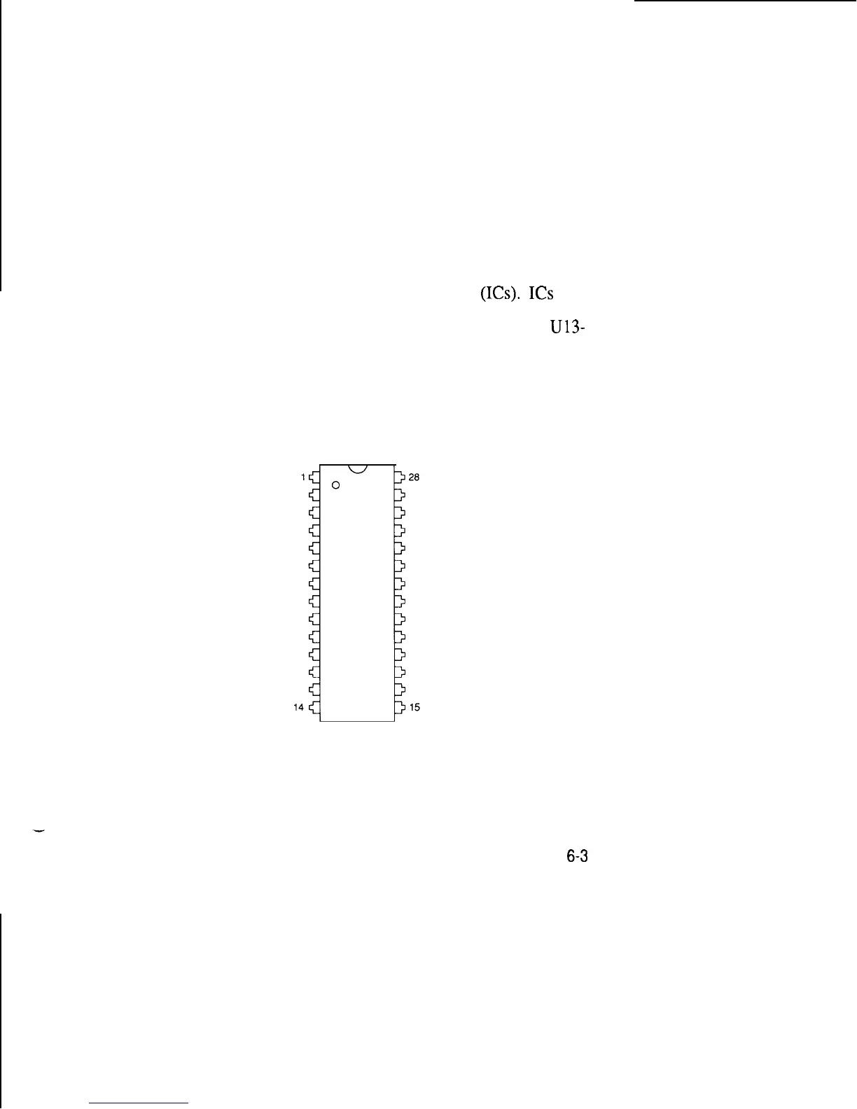
The figure below shows how pins are numbered on a 28-pin
DIP. The top surface is marked by a notch or dimple. Looking
down at it, pins are numbered counter-clockwise starting to the
left of the mark with pin 1.
6-3