If for some reason you do not like this starting point,
you can press the SUGGEST
softkey
and then the
ENTER key to look at other recommended starting
points for GFI. Then you can press the
GFI
key
followed by the RUN
softkey
and enter another GFI
starting point using the cursor control keys and the
operator’s display.
6.
When you are ready to begin fault isolation at the
point in the RUN GFI command, press the ENTER
key. If the GFI database exists for the selected
UUT, GFI takes over and starts backtracing from the
selected starting point on the UUT. For this
example, the display now becomes:
RUN GFI UUT DEMO REF U3 PIN 1
CLIP u3
PRESS BUTTON ON I/O MOD WHEN READY
7. Attach a clip over the component specified (U3 in
this case) and press the ready button on the clip
module used.
8.
GFI tests and displays the condition of all pins of U3
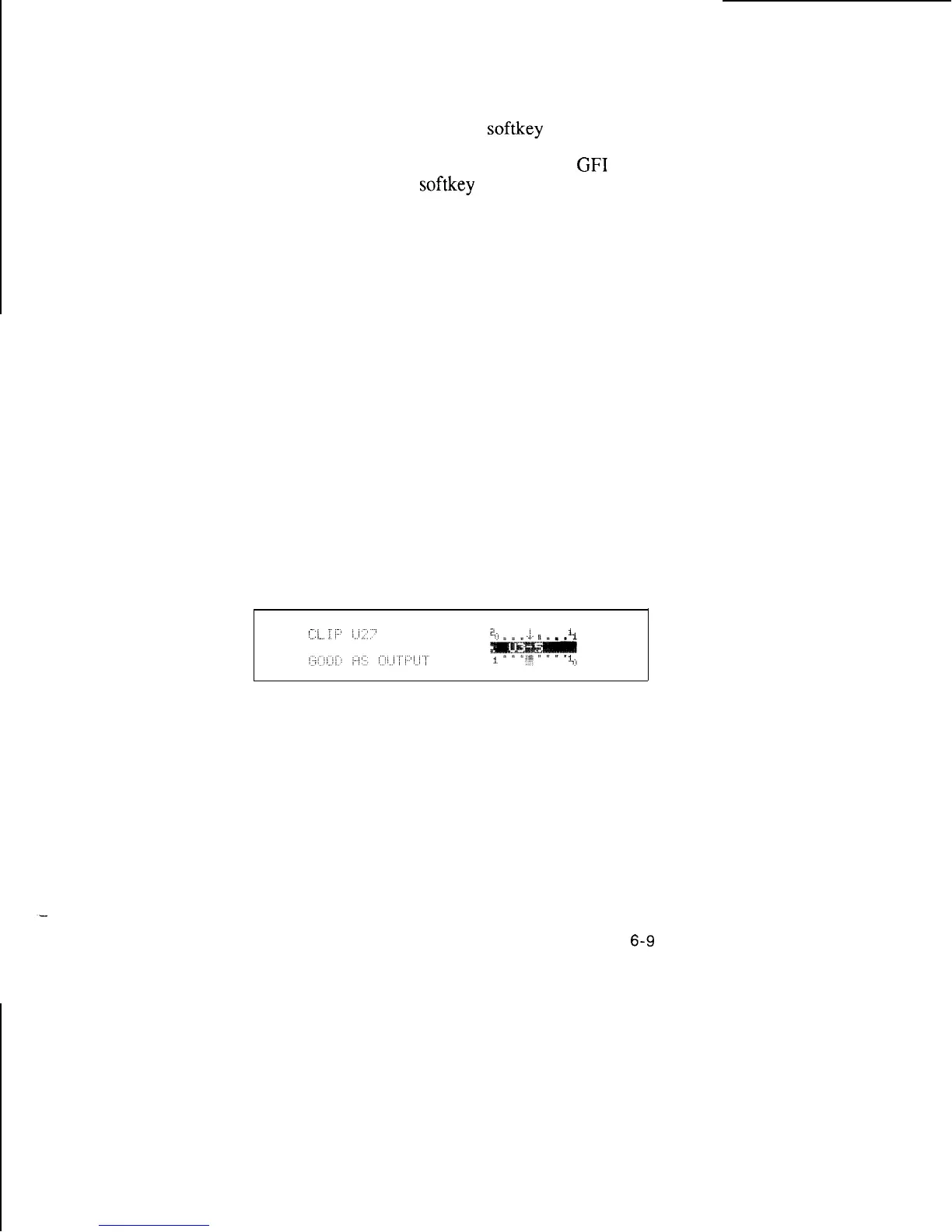
and recommends the next component to test. A
typical display is shown below:
The arrow on the displayed IC pins indicates bad
input, output, or bidirectional pins. The words in the
lower left comer display the status of each pin as the
cursor is moved from pin to pin with the right arrow
and left arrow keys.
6-9