13
(right) if there there are more items to view. This
applies to data screens not “scroll-select”
screens.”
⇒ Press the Up key to navigate to the
(top right)
and press Select to close the current screen.
⇒ Certain screens also display a wrench
icon left
of the
. Select this icon to access the
configuration screen for that function.
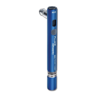
NetTool LED Indicators
NetTool has two tricolor LED
indicators on each side to reflect
link and health information at a
glance.
LINK/CLSN/ERR LED
Green
= Link pulse present
Yellow
= Collisions occurring
Red
= Errors occurring
afq26f.eps
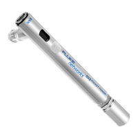
Utilization LED
The bottom tricolor LED (UTIL) indicates utilization
percentages for each side.
Green
= utilization levels below 40%
Yellow
= levels between 40% and 70%
Red
= levels greater than 70%
Serial Connection
Connecting NetTool to a PC via the customized serial
cable (supplied PN 1541340) allows you to:
• Download software (read
NetTool Updates,
etc.
on page 38 for details).
• Enable options.
• Save screens.
• Use NetTool Blaster and NetTool Toolkit
programs supplied on the CD-ROM (check
the
Reporter
and
Ping Catalog
sections).