27
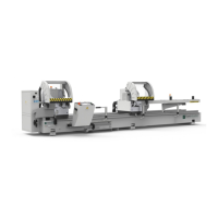
BLITZ
G BG B
G BG B
G B
5.4 LEVELLING
The machine sits on the ground on adjustable feet (see Fig. 05-12). These feet can vary in number depending
on the length of the machine.
BLITZ m. 5 = 8 feet
BLITZ m. 6.6 = 10 feet
The machine is shipped with the adjustable feet fully screwed in, concealed inside the “U”-shaped cross member
housing.
Remove the 2 brackets “A” - Fig. 05-12A that secure the mobile head to the machine bed.
Use a centesimal spirit level with tolerance of between 0.02 and 0.05 mm per metre. Levelling must take place
crosswise (where maximum precision is required) and lengthwise (where the machine does not need to be
perfectly level but the error should however be constant over the whole of the machine length).
N.B. The spirit level should always be placed on the worktable of the MH.
Rest the machine feet on the ground using the screw adjusters “1” - Fig. 05-12 and with the relative lock nuts
“2” - Fig. 05-12 loose.
1st PHASE
With the MH next to the FH, level lengthwise, placing the spirit level as in Fig. 05-13.
Move the MH manually to the mid position between the feet up to the position between the penultimate and last
foot and then level lengthwise in each of these positions (see Fig. 05-14) making sure the error is constant.
Move the MH manually to the RIGHT up to the end of the bench and then level crosswise, placing the spirit
level as in Fig. 05-15; if necessary use the RIGHT front and rear adjusters to make it perfectly level.
Move the MH manually to the FH and level crosswise placing the spirit level as in Fig. 05-16; if necessary use
the LEFT front and rear adjusters to make it perfectly level.
Move the MH manually to the centre of the machine where the centre feet are and level crosswise placing the
spirit level as in Fig. 05-17; if necessary use the centre front and rear adjusters to make it perfectly level.
2nd PHASE
Move the MH manually to the FH and carry out the operations again in the same sequence as described in the
1st phase in order to obtain more precise levelling.
Once the levelling operations are complete, tighten all the lock nuts of the foot adjusters (see Fig. 05-12).
Switch on the power and air to the machine (see chap. 7 - ELECTRICAL AND PNEUMATIC CONNECTION),
then enable it by pressing “1” - Fig. 06-02 in order to raise the safety hoods. Once the hoods are raised, cutoff
power and air to the machine again.