64
G BG B
G BG B
G B
BLITZ
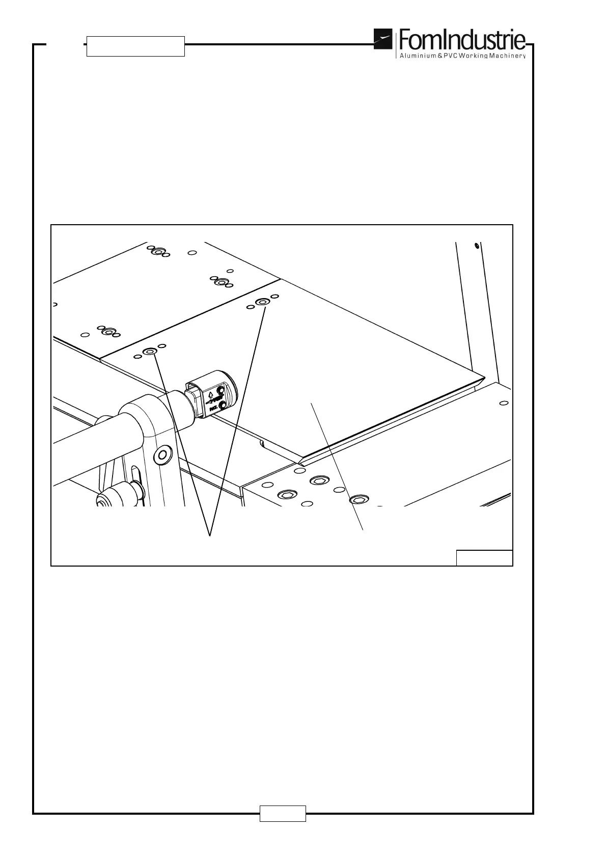
Now table ‘E’ - Fig. 09-31 can be fitted for making 90° step-by-step cuts.
The table is inserted over support ‘A’ - Fig. 09-29 and rests up against pin ‘B’ - Fig. 09-30
The table is secured in place by tightening the 2 fixing screws ‘F’ - Fig. 09-31.
CAUTION - IMPORTANT
Table ‘E’ - Fig.09-31 must ONLY be used when making 09° step-by-step cuts with the fixed head blade.
For non 90° cuts using the fixed head blade, the table must ALWAYS be removed otherwise it could be cut by
the blade.
F
E
09-31
If the ‘step-by-step’ program is used with a safety photocell barrier, for fitting the photocells see the leaflet
“Photocell kits for step-by-step program” enclosed with this manual