13
2-2. MFR-3100EX Rear Panel
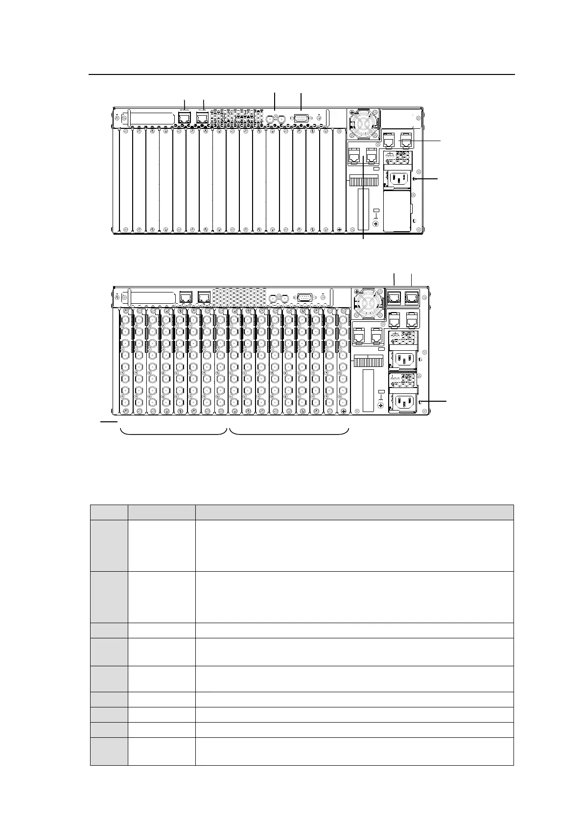
* The above figure shows an MFR-3100EX with MFR-8SDI, MFR-8SDO, MFR-31CPU and
MFR-31PS cards installed.
Ethernet ports for connection to MFR Remote Control Units and MFR-
GPI (10/100BASE-TX, RJ-45)
(1) MFR-LAN2 (for MFR-3100EX)
(2) MFR-LAN1 (for MFR-31CPU)
Ethernet ports for connection to PC or other external unit
(10/100/1000BASE-T, RJ-45)
(1) PC-LAN2 (for MFR-3100EX)
(2) PC-LAN1 (for MFR-31CPU)
Used for alarm output
► See Sec. 2-2-1. "Interfaces."
Used to connect Power Supply Unit 1 (standard equipment) to an AC
power source
Used to connect Power Supply Unit 2 (optional) to an AC power source
Used for installing input cards
Used for installing output cards
Used to input a reference signal (BB or Tri-level sync)
(With loop-through. Terminate with 75-ohm terminator, if unused.)
PS1
PS2
AC100-240V 50/60Hz IN
AC100-240V 50/60Hz IN
MFR-3100EX
1
SLOT
3 4
2
MFR-31VP
INPUT OUTPUT
1 2 3 45 6 78 1 23 45 67 89
MFR-LAN PC-LAN
REF IN ALARM
PS1
PS2
2
3
4
5
6
7
8
1
2
3
4
5
6
7
8
1
2
3
4
5
6
7
8
1
2
3
4
5
6
7
8
1
2
3
4
5
6
7
8
1
2
3
4
5
6
7
8
1
2
3
4
5
6
7
8
1
2
3
4
5
6
7
8
1
2
3
4
5
6
7
8
1
2
3
4
5
6
7
8
1
2
3
4
5
6
7
8
1
2
3
4
5
6
7
8
1
2
3
4
5
6
7
8
1
2
3
4
5
6
7
8
1
2
3
4
5
6
7
8
1
2
3
4
5
6
7
8
1
2
3
4
5
6
7
8
1
M
FR
-3100EX
AC
100-240V 50/60H
z IN
SLOT
INPUT OUTPUT
1 2
MFR-31VP
OUTOUT
98
OUT
7
OUT
6
OUT
MFR-LAN PC-LAN
MFR-31CPU
3 4
1 2 3 45 6 78 1 23 45 6 78 9
AC
100-240V 50/60H
z IN
OUTOUTININININININ
543
OUT
2
OUT
187654321
ININ
MFR-LAN PC-LAN
REF IN
ALARM
01 02 03 04 05 06 07 08 09 10 11 12 13 14 15 16 17