34
3. System Configuration Example
3-1. Basic Configuration
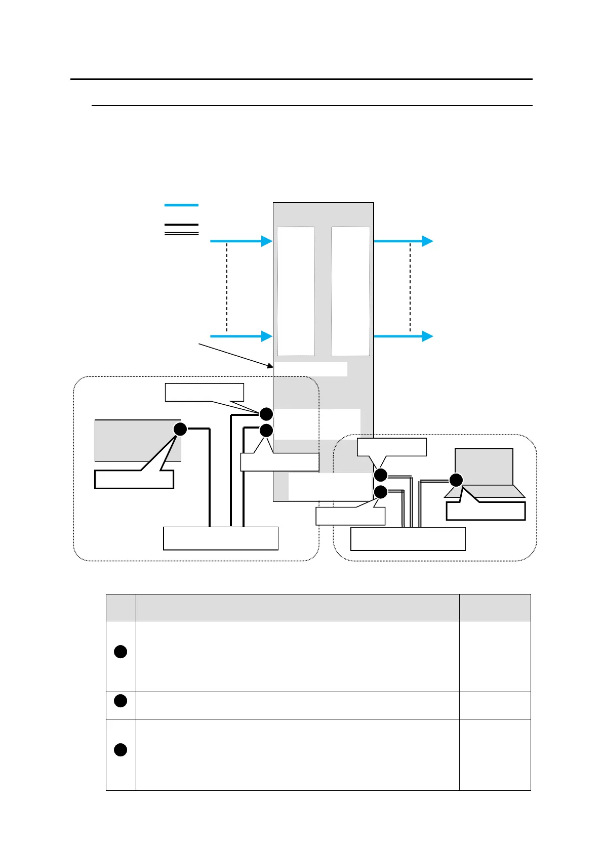
The block diagram below shows an example of the basic MFR routing system that consists of an
MFR-3100EX, Remote Unit and the Web-based Control accessed from a computer.
Make sure to connect both MFR-LAN1 (MFR-31CPU) and MFR-LAN2 (MFR-3100EX) to a LAN
respectively for CPU redundancy. Their LAN connections must be separated from the network
segment of PC-LAN and other devices. (Default IP addresses (Net mask: 255.255.255.0) are used
in the configuration example below.)
◆ LAN Port Settings
RU Front Panel
(Sec. in MFR-RU Series Operation Manual)
MFR-39RUA: “Setting Mode Menu (MFR-39RUA)”
MFR-18RUA: “Setup Menu (MFR-18RUA)”
MFR-16RUTA: “Setup Menu (MFR-16RUTA)”
MFR-8RUA: “Setup Menu (MFR-8RUA)”
Other RUs: “Setup Menu (MFR-16/40RU, MFR-16RUD,
MFR-16/32/64RUW)”
MFR-39RUA: “Setting Mode Menu (MFR-39RUA)” (Display only)
MFR-18RUA: “Setup Menu (MFR-18RUA)” (Display only)
MFR-16RUTA: “Setup Menu (MFR-16RUTA)” (Display only)
MFR-8RUA: “Setup Menu (MFR-8RUA)” (Display only)
Other RUs: “Setup Menu (MFR-16RU/40RU, MFR-16RUD,
MFR-16/32/64RUW)”(Display only)