Drive Axles with Differential
Lock
Drive Axles with Main Differential
Lock
The main differential lock is a driver-controlled trac-
tion device operated from the vehicle cab. A dash
switch controls the side to side lock-up of the rear
axle, supplying equal traction to both sides. On tan-
dem axles there are three possible differential lock
options:
•
Forward-rear carrier only
•
Rear-rear carrier only
•
Both rear carriers.
An indicator light comes on when the differential lock
is engaged. An optional buzzer can also be used to
indicate differential lock engagement.
The main differential lock provides maximum traction
under slippery conditions. When the differential lock
is engaged, the clutch collar completely locks the
differential case, gearing, and axle shafts together,
maximizing traction of both wheels and protecting
against spinout. Under normal traction conditions, do
not engage the differential lock. Operate the axle
with differential action between both wheels.
WARNING
Be especially careful when driving under slippery
conditions with the differential locked. Though
forward traction is improved, the vehicle can still
slip sideways, causing possible loss of vehicle
control, personal injury, and property damage.
Main Differential Lock Operation
To lock the main differential and obtain maximum
traction under slippery conditions, move the control
switch to the lock position.
NOTE: On some vehicles, the differential lock
system is connected through the low speed
range of the transmission. If this system is used,
the transmission must be in the low speed
range for the differential to fully lock.
If the vehicle is moving, maintain a constant vehicle
speed while engaging the differential lock. Briefly let
up on the accelerator to relieve torque on the gear-
ing, allowing the differential to fully lock. The indica-
tor light should come on and the buzzer should
sound on vehicles so equipped. When the differential
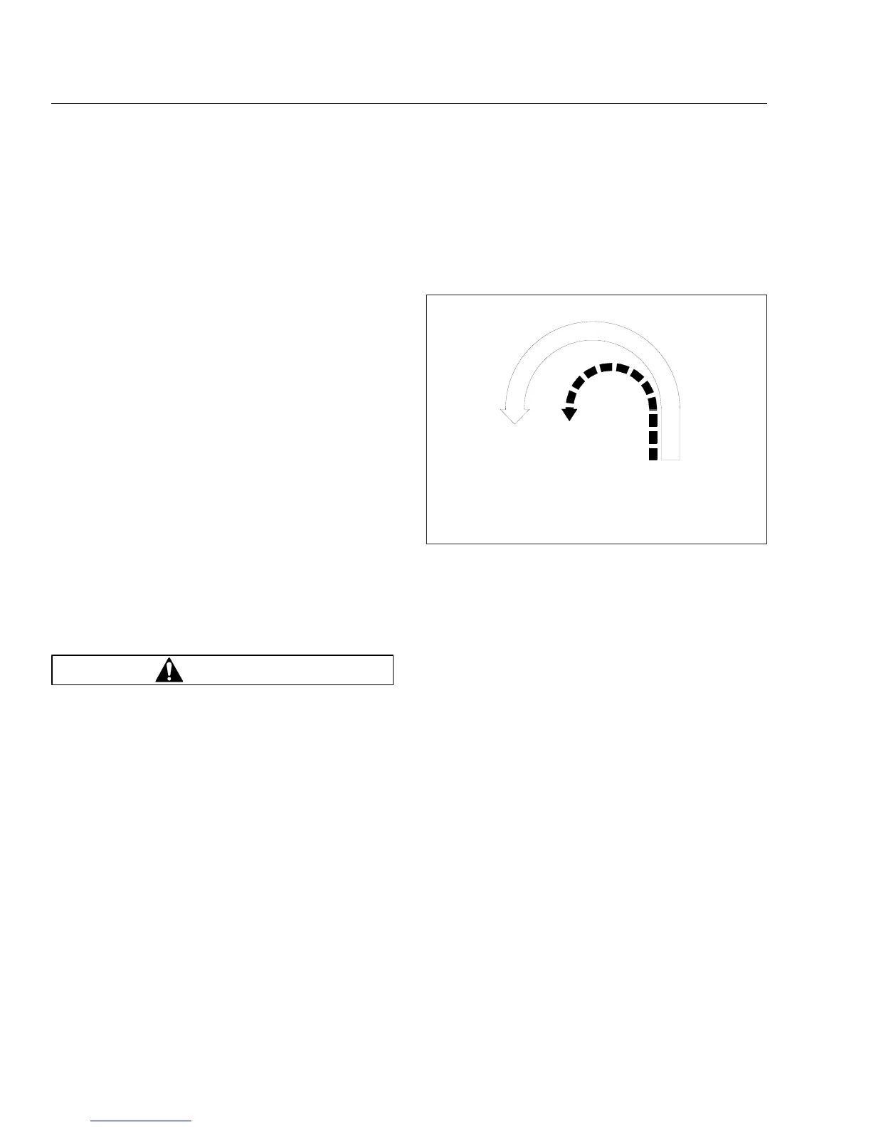
is fully locked, the turning radius will increase be-
cause the vehicle understeers. See
Fig. 15.1. Drive
cautiously and do not exceed 25 mph (40 km/h).
To unlock the main differential, move the control
switch to the unlock position. Briefly let up on the
accelerator to relieve torque on the gearing, allowing
the differential to fully unlock.
NOTE: If the differential lock system is con-
nected through the low speed range of the
transmission, shifting out of low speed range will
also unlock the differential.
When the differential lock disengages, the indicator
light will go off and the buzzer will stop.
Tandem Drive Axles with Interaxle
Differential
Tandem drive axles with an interaxle differential have
a lockout feature. Differential lockout is controlled by
a switch (
Fig. 15.2) on the control panel.
In the UNLOCK position, there is differential action
between the two axles. The differential compensates
for different wheel speeds and variations in tire size.
Keep the interaxle differential unlocked for normal
driving on roads where traction is good.
In the LOCK position, the interaxle differential is
locked out and the driveshaft becomes a solid con-
nection between the two axles. Power entering the
02/09/96
f350079a
A
B
A. Turning Radius When Differential is Locked
(engaged)—Understeer Condition
B. Turning Radius When Differential is Unlocked
(disengaged)
Fig. 15.1, Turning Radius
Drive Axles
15.1