Vehicle Power Supply
WARNING
Do not attempt to modify, add, splice, or remove
electrical wiring on this vehicle. Doing so could
damage the electrical system and result in a fire
that could cause serious personal injury or prop-
erty damage.
Power Distribution
There are four power distribution modules in the ve-
hicle: the main power distribution module (PDM), the
auxiliary PDM, the powertrain PDM, and the power-
net distribution box (PNDB).
The main PDM contains the circuit breakers and
fuses required to protect the vehicle. It is located in
the top of the right-hand dash, and is accessed by
removing the four fasteners in the top of the dash
panel.
The auxiliary PDM is located on the B-pillar access
door, behind the driver’s seat. It controls power to the
HVAC system, the sleeper, and anti-lock braking.
The powertrain PDM is mounted off the driver’s-side
frontwall in the engine compartment. It controls
power to the engine, aftertreatment system, transmis-
sion, and other powertrain-related circuits.
The PNDB is mounted on the cab frontwall near the
steering column. It supplies power to the powertrain
PDM, the main PDM and other cab functions, includ-
ing the clock.
Load Disconnect Switch
WARNING
Turning the load disconnect switch to the OFF
position does not disconnect the connection be-
tween the battery and the starter. To work on the
vehicle safely, the negative leads must be discon-
nected from the battery.
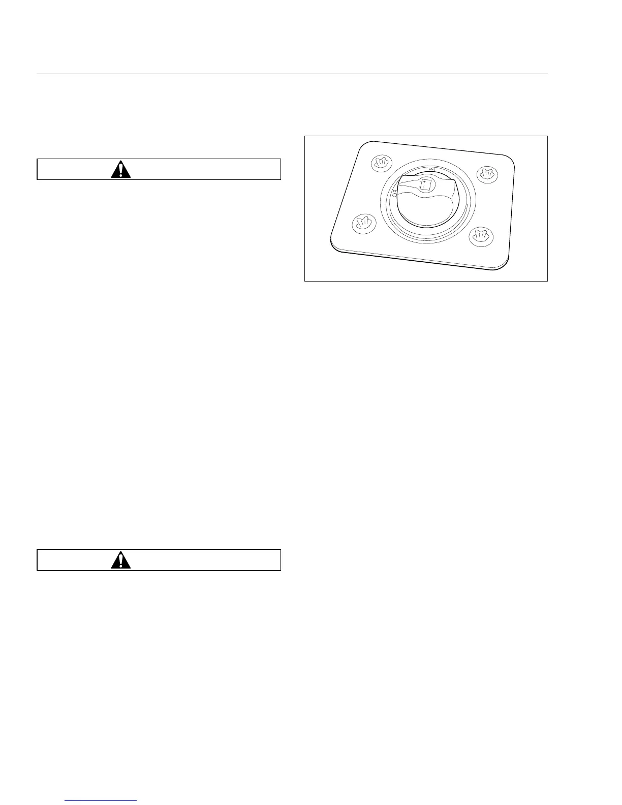
The load disconnect switch is used to avoid exces-
sive draw on the battery when the vehicle is parked
for an extended period of time. See
Fig. 3.1. When
the load disconnect switch is set to OFF, it signals
the PNDB to disconnect battery power to powertrain
and accessory loads. The power to the
aftertreatment-system control module is disconnected
after the DEF purge function is completed.
The load disconnect switch is mounted in one of two
locations:
•
inside the cab on the left side of the driver’s
seat (left-hand-drive vehicle);
•
on the battery box
IMPORTANT: The ignition should be turned OFF
before turning the load disconnect switch to ON
or OFF.
Low Voltage Disconnect, Optional
The optional Sure Power Low Voltage Disconnect
(LVD) system monitors battery power when accesso-
ries are being used while the engine is shut down.
The system automatically turns off cab and sleeper
accessories when voltage drops to 12.3 volts, to en-
sure that there is enough battery power to start the
vehicle. An alarm sounds for one minute before ac-
cessories are turned off. If no action is taken within
that minute, the LVD module will shut off power to
predetermined cab and sleeper circuits. These cir-
cuits will remain off until the LVD measures 13.0
volts applied to the system, which can be achieved
by starting the engine. After the engine is started, the
system will reset.
Vehicles are equipped with an LVD label on the
drivers-side sun visor, indicating the presence of the
system.
05/13/2009 f545527
Fig. 3.1, Load Disconnect Switch
Electrical System
3.1