NOTICE
Coolant must be filled to the COLD MAX line of
the surge tank. Low coolant could result in en-
gine overheating, which could cause engine dam-
age.
5.1
If the coolant is low, fill the surge tank to
the MAX line with a 50/50 mixture of water
and the type of antifreeze currently in-
stalled in your vehicle.
5.2
If the surge tank was empty, start the en-
gine after refilling and check the level
again when the engine is at operating
temperature.
6.
Inspect visible engine wiring for damage or
looseness. Check for loose wiring, chafed insula-
tion, and damaged or loose hold-down clamps.
7.
Inspect visible frame rails for missing bolts, shiny
areas, or rust streaks.
Cab Inspection
1.
Push the reset button on the dash-mounted air
intake restriction indicator, if equipped.
2.
With the ignition switch in the OFF position,
check the air-pressure warning system.
2.1
If not previously drained, drain the air res-
ervoirs using moderate brake applications
until pressure in both reservoirs is less
than 70 psi (483 kPa).
2.2
Turn the ignition to the ON position. The
ICU will complete a full gauge sweep and
bulb check, and an audible warning will
sound. Ensure the low air pressure lamp
(BRAKE AIR) remains illuminated and an
audible warning continues to sound after
the gauge sweep is complete.
3.
Check air governor cut-in and cut-out pressures.
3.1
Start the engine and ensure the BRAKE
AIR lamp goes out and the buzzer si-
lences when pressure reaches approxi-
mately 70 psi (483 kPa) in both air reser-
voirs.
The air governor should cut out at ap-
proximately 120 psi (827 kPa). For ve-
hicles with an optional dryer reservoir
module (DRM), the cut-out pressure is
approximately 130 psi (896 kPa).
3.2
With the engine idling, apply the brake
pedal several times. The air governor
should cut in when pressure in the primary
air reservoir (top air gauge) reaches ap-
proximately 100 psi (689 kPa).
4.
Check air pressure build-up time.
05/21/2007
1
f462079
NOTE: Typical reservoir shown; configurations may
vary.
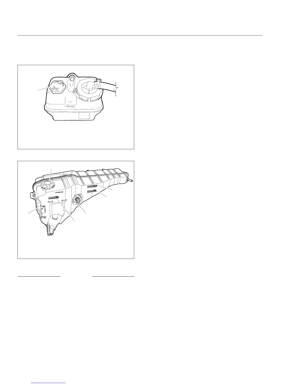
1. Filler Cap
Fig. 20.4, Power Steering Fluid Reservoir
1
2
f500390
3
4
4
02/05/2013
5
1. Pressure Relief Cap
2. Filler Cap
3. COLD MAX Fill Line
4. COLD MIN Fill Line
5. Coolant Level Sensor
Fig. 20.5, Coolant Surge Tank
Pre- and Post-Trip Inspections and Maintenance
20.5